Goodrive350 series high-performance multi-function inverter Chapter 6
-126-
Detailed parameter description
stop): Before the DC brake, the inverter will block
output, and after the demagnetization time elapses,
DC brake will start. This function is used to prevent
overcurrent fault caused by DC brake during high
speed.
DC brake current after stop: it means the DC brake
force applied, the larger the current, the stronger the
DC brake effect.
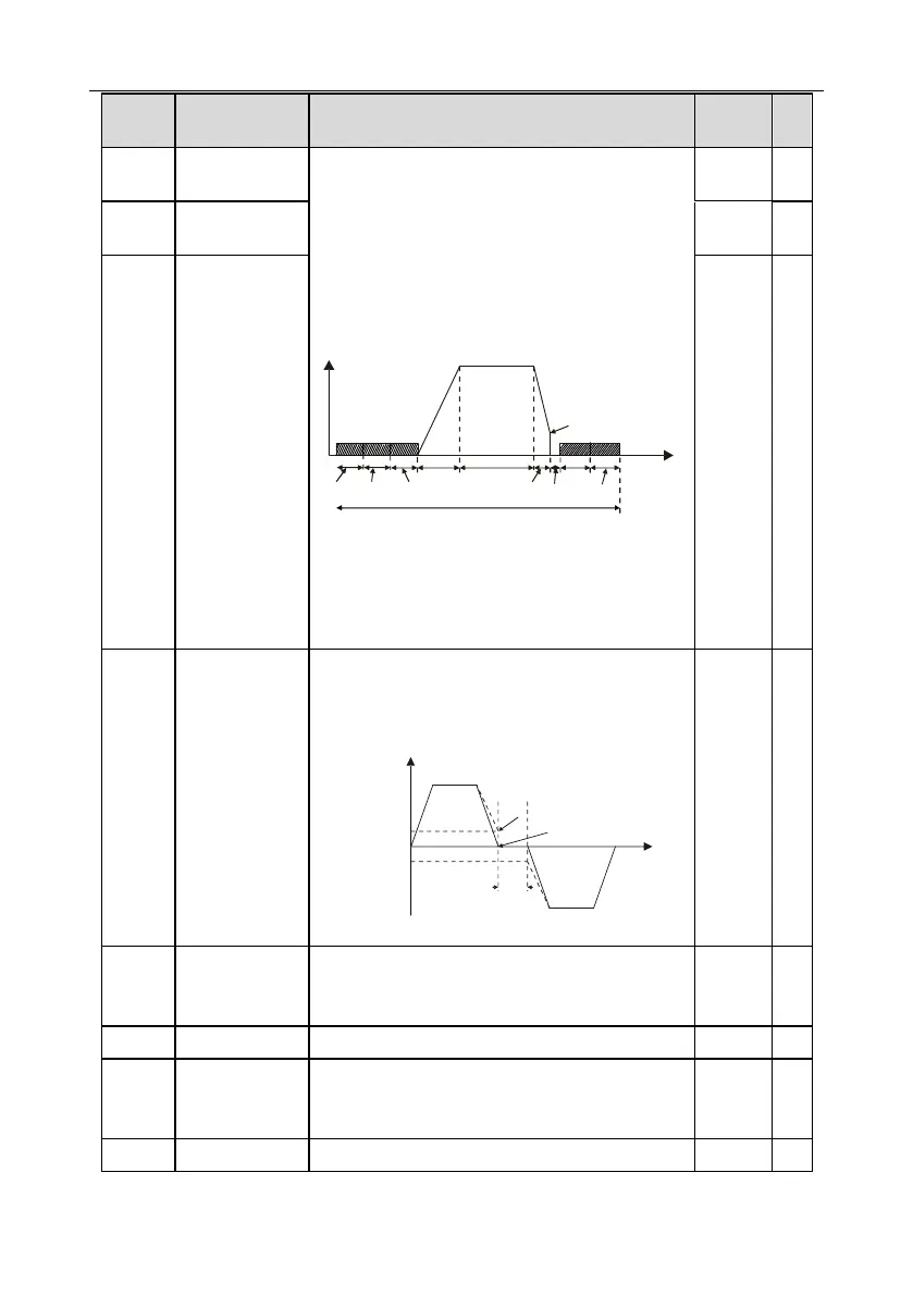
P01.04
Acceleration
P13.14
P01.23
Constant speed
In running
Deceleration
P01.10
P13.15
P01.12
P01.09
Time t
Setting range of P01.09: 0.00Hz–P00.03 (max.
output frequency)
Setting range of P01.10: 0.00–30.00s
Setting range of P01.11: 0.0–100.0%
Setting range of P01.12: 0.0–50.0s
Deadzone time of
forward/reverse
rotation
This function code refers to the transition time of the
threshold set by P01.14 during setting
forward/reverse rotation of the inverter, as shown
below.
Output frequency f
Forward
Reverse
Deadzone
time
Time t
Starting
frequency
Switch over after
zero frequency
Switch over after
starting frequency
Setting range: 0.0–3600.0s
Forward/reverse
rotation
switch-over mode
0: Switch over after zero frequency
1: Switch over after starting frequency
2: Switch over after passing stop speed and delay
Stop speed
detection mode
0: Set value of speed (the only detection mode valid
in SVPWM mode)
1: Detection value of speed

 Loading...
