Goodrive350 series high-performance multi-function inverter Chapter 6
-132-
Detailed parameter description
synchronous
motor 1
(reserved)
Overload
protection of
motor 1
0: No protection
1: Common motor (with low-speed compensation).
As the cooling effect of common motor will be
degraded in low speed, the corresponding electronic
thermal protection value should also be adjusted
properly, the low compensation here means to lower
the overload protection threshold of the motor whose
running frequency is below 30Hz.
2: Frequency-variable motor (without low speed
compensation). As the cooling effect of
frequency-variable motor is not affected by the
rotating speed, there is no need to adjust the
protection value during low speed running.
Overload
protection
coefficient of
motor 1
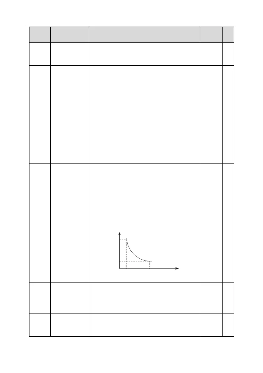
Motor overload multiples M=Iout/(In×K)
In is rated motor current, lout is inverter output
current, K is motor overload protection coefficient.
The smaller the K, the larger the value of M, and the
easier the protection.
M=116%: protection will be applied when motor
overloads for 1h; M=200%: protection will be applied
when motor overloads for 60s; M>=400%: protection
will be applied immediately.
1m
1h
116
%
200%
Time t
Motor overload multiple
Setting range: 20.0%–120.0%
Power display
calibration
coefficient of
motor 1
This function adjusts the power display value of
motor 1 only, and it does not affect the control
performance of the inverter.
Setting range: 0.00–3.00
Parameter
display of motor 1
0: Display as per motor type; under this mode, only
parameters related to current motor type will be
displayed.

 Loading...


