This group of function code defines the V/F curve of
motor 1 to satisfy different load characteristics
needs.
0: Straight V/F curve; fit for constant-torque load
1: Multi-point V/F curve
2: Torque down V/F curve (1.3
th
order)
3: Torque down V/F curve (1.7
th
order)
4: Torque down V/F curve (2.0
nd
order)
Curve 2–4 are suitable for torque-variable load of fan
pump and similar equipment. Users can make
adjustment based on load characteristics to achieve
optimal energy-saving effect.
5: Customized V/F (V/F separation); under this
mode, V is separated from f. Users can adjust f
through the frequency reference channel set by
P00.06 to change the curve characteristic, or adjust
V through the voltage reference channel set by
P04.27 to change the curve characteristics.
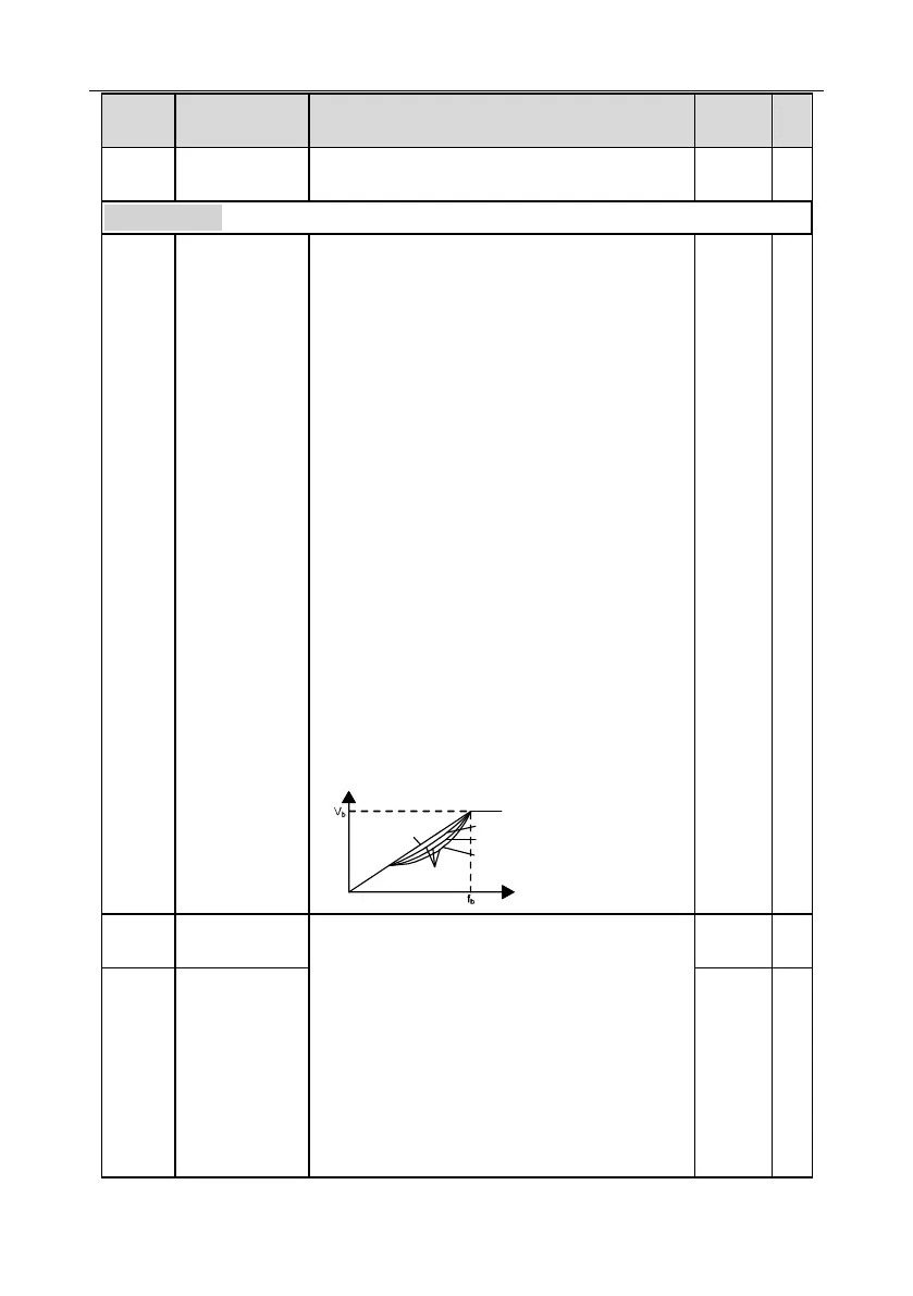
Note: The V
b
in the figure below corresponds to
rated motor voltage, and f
b
corresponds to rated
motor frequency.
Output voltage
Output frequency
Linear type
Square type
Torque step-down V/F curve (1.3
th
order)
Torque step-down V/F curve (1.7
th
order)
Torque step-down V/F curve (2.0
nd
order)
In order to compensate for low-frequency torque
characteristics, users can make some boost
compensation to the output voltage. P04.01 is
relative to the max. output voltage V
b.
P04.02 defines the percentage of cut-off frequency
of manual torque boost to the rated motor frequency
f
b.
Torque boost can improve the low-frequency
torque characteristics of V/F.
Users should select torque boost based on the load,
eg, larger load requires larger torque boost,

 Loading...


