Goodrive350 series high-performance multi-function inverter Chapter 6
-162-
Detailed parameter description
selected by multi-function digital input terminal (P05
group). The acceleration/deceleration time of the
inverter is the first group by default.
Setting range: 0.0–3600.0s
Running
frequency of
jogging
This function code is used to define the reference
frequency of the inverter during jogging.
Setting range: 0.00Hz–P00.03 (max. output
frequency)
Acceleration time
of jogging
Jogging acceleration time is the time needed for the
inverter to accelerate from 0Hz to max. output
frequency (P00.03).
Jogging deceleration time is the time needed from
decelerating from the max. output frequency
(P00.03) to 0Hz.
Setting range: 0.0–3600.0s
Deceleration time
of jogging
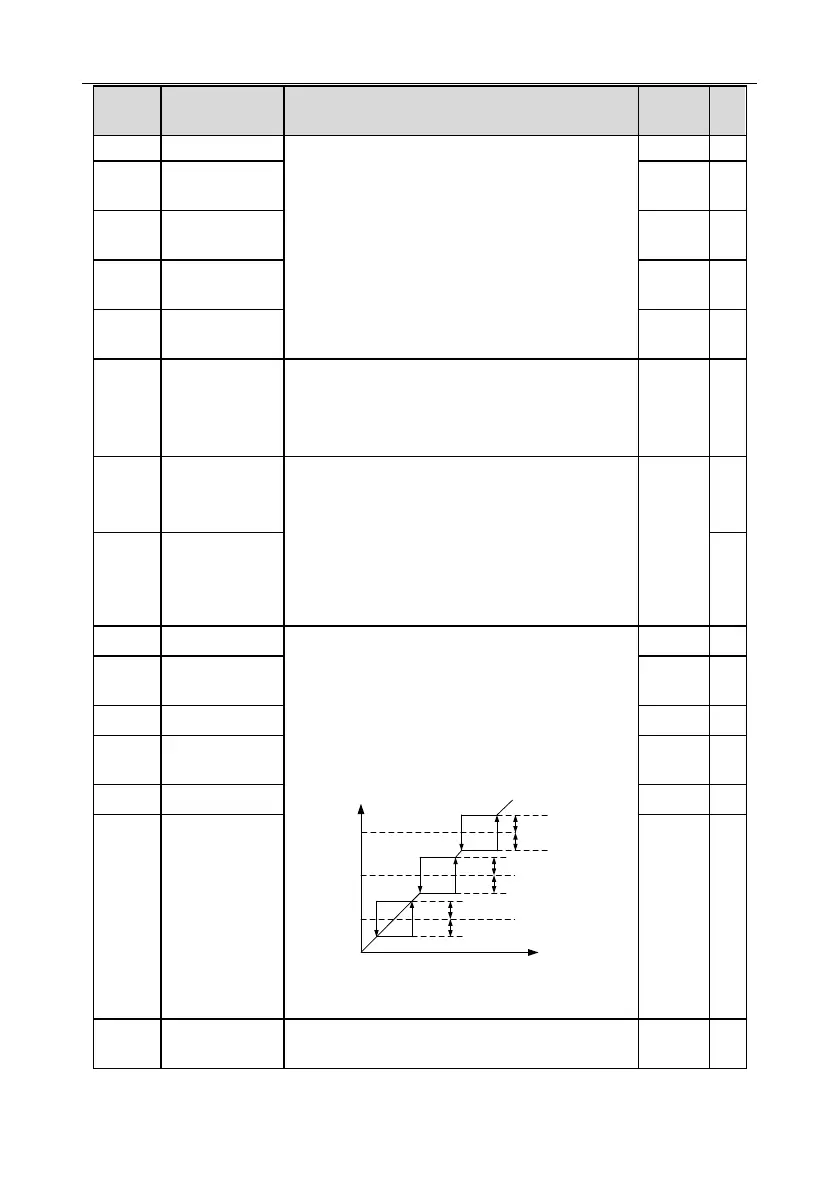
When the set frequency is within the range of jump
frequency, the inverter will run at the boundary of
jump frequency.
The inverter can avoid mechanical resonance point
by setting the jump frequency, and three jump
frequency points can be set. If the jump frequency
points are set to 0, this function will be invalid.
Set frequency f
Time t
Jump
frequency 2
1/2* jump amplitude 2
1/2* jump amplitude 2
Jump
frequency 1
1/2* jump amplitude 1
1/2* jump amplitude 1
Jump
frequency 3
1/2* jump amplitude 3
1/2* jump amplitude 3
Setting range: 0.00Hz–P00.03 (max. output
frequency)
Jump frequency
amplitude 1
Jump frequency
amplitude 2
Jump frequency
amplitude 3
0.0–100.0% (relative to set frequency)

 Loading...


