P23.00–P23.05 fit for vector control mode only.
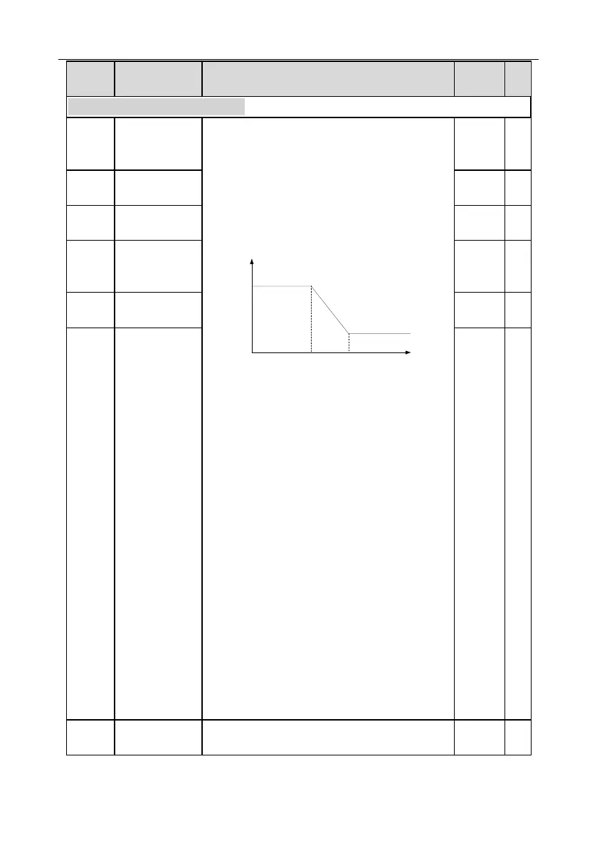
Below switch-over frequency 1 (P23.02), the speed
loop PI parameters are P23.00 and P23.01. Above
switch-over frequency 2 (P23.05), the speed loop PI
parameters are P23.03 and P23.04; in between
them, the PI parameters are obtained by linear
variation between two groups of parameters, as
shown in the figure below.
The speed loop dynamic response characteristics of
vector control can be adjusted by setting the
proportional coefficient and integral time of speed
regulator. Increase proportional gain or decrease
integral time can accelerate dynamic response of
speed loop, however, if the proportional gain is too
large or integral time is too small, system oscillation
and large overshoot may occur; if proportional gain
is too small, stable oscillation or speed offset may
occur.
Speed loop PI parameter is closely related to the
system inertia, users should make adjustment
according to different load characteristics based on
the default PI parameter to fulfill different needs.
Setting range of P23.00: 0.0–200.0
Setting range of P23.01: 0.000–10.000s
Setting range of P23.02: 0.00Hz–P23.05
Setting range of P23.03: 0.0–200.0
Setting range of P23.04: 0.000–10.000s
Setting range of P23.05: P23.02–P00.03 (max.
output frequency)

 Loading...


