SV-DA200 series AC servo drive Control mode applications
-54-
Electromagnetic
brake release
signal
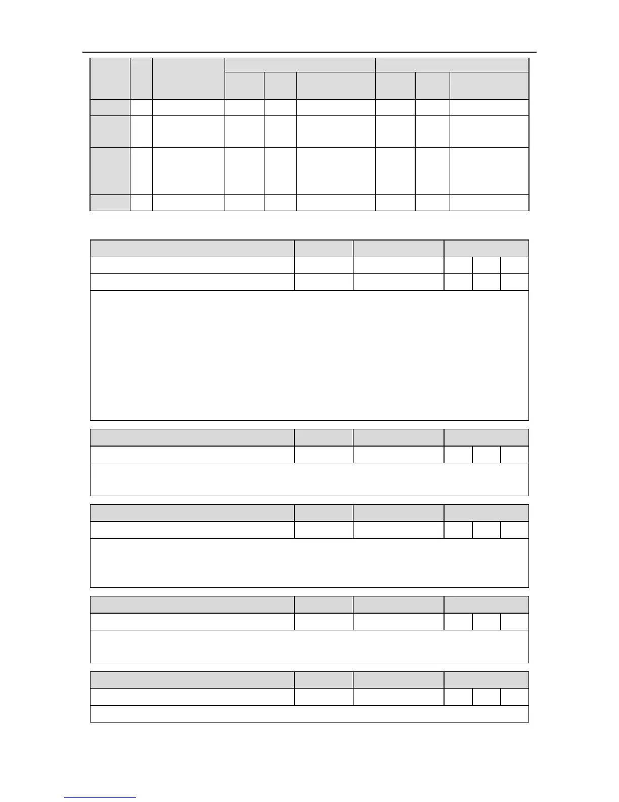
4.4.4.1 Function description of the digital input:
Positive direction drive disabled
Negative direction drive disabled
This function input is the drive prohibition against positive/negative direction. The concrete action
is related to the setting of P3.40 [travel limit switch setting]:
When P3.40 is set to 0 and positive direction input is disabled, the motor stops at the current
position, only negative direction command input can be accepted. If the negative direction drive
input is disabled, the motor stops at the current position, only positive direction command input
can be accepted.
P3.40 is 1, the function is invalid;
P3.40 is 2, and prohibition of positive/negative drive input is valid, the drive alarms.
This function is the control signal of the servo enabling/disabling.
If it is valid, the drive will provide power to the motor; if invalid, the drive will cut off connection.
This function is the control signal of alarm clearing when the drive alarms.
Some alarms cannot be cleared by this function. Please refer to chapter 10.4 for detailed
information.
This function is the control signal of mode switching when P0.03 is 3, 4 and 5.
When the control mode is 0, 1, 2, 6 and 7 the function input is invalid.
This function is the control signal of 1
st
and 2
nd
gain switching.
 Loading...