SV-DA200 series AC servo drive Function codes
-139-
Voltage protection of
analog input 1
This parameter is used to set the overvoltage protection of analog input 1.
If the absolute value of R1.05 exceeds the setting value, the system will report fault.
Note:
1. The default value 0 means no overvoltage protection;
2. The input voltage should be no more than 10V, otherwise damage may occur to the drive.
This parameter can be used to adjust the analog input 2 to improve the effective accuracy of
analog input.
The setting method is the same with P3.20.
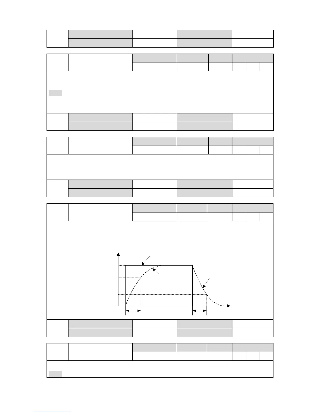
This parameter is used to set the time constant of the first order low-pass filter corresponds to the
command. Setting this parameter can smooth the changing of actual output command when the
command changes violently. Please refer to the figure below:
Command before filtering
AD2
Time
Command after filtering
Command after filtering
P3.24P3.24
Vc
0.632Vc
0.368Vc
Voltage protection of
analog input 2
This parameter is used to set the overvoltage protection value of analog input 2.
Note:
 Loading...