39YLS-K
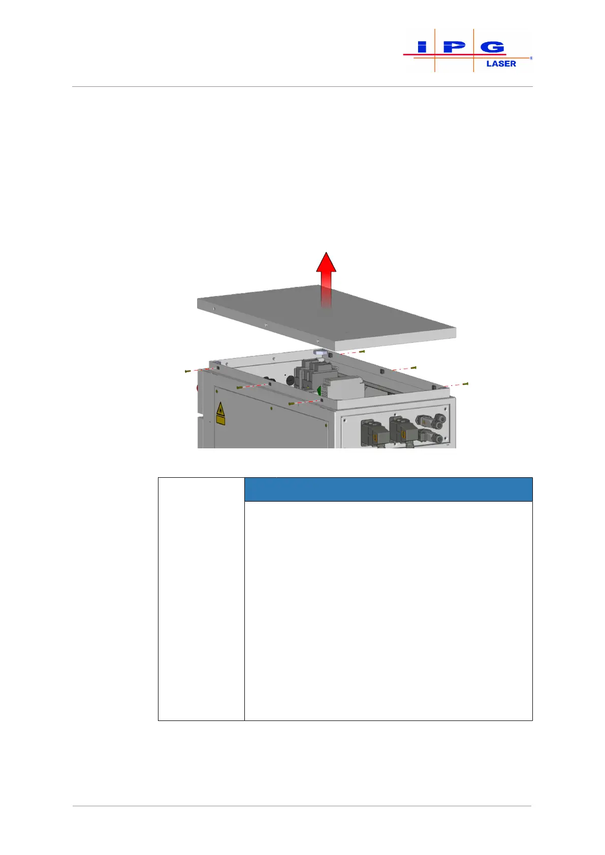
1. Remove the M5 countersunk screws on the left and right side of
the upper laser cabinet cover.
2. Carefully lift the upper cover.
The upper cover is connected to the frame of the laser cabinet by a grounding
wire. The grounding wire is fastened to the grounding connector (star point) with a
flat connector.
3. Disconnect the flat connector of the grounding wire from the
grounding connector on the frame.
4. Remove the upper cover.
Figure13: Removing the upper cover
NOTICE
Damage to the electronics due to falling objects
The upper cover of the laser cabinet protects the
electronics underneath. The removal of the upper
cover reduces the protection class of the cabinet to
IP00 (no protection). The electronics of the laser can
be damaged by falling objects or penetrating water.
This type of damage is not covered by the IPG war-
ranty.
ð Take care not to allow any objects to fall into
the laser.
ð Take care not to allow any liquids to enter the
laser.
ð Restore the upper cover immediately after the
transport.
5. Screw the four eye bolts into the provided threaded plates (M12
thread).
You can now use a suitable lifting device to lift the product out of the transport
packaging and bring it to the installation site.
| Delivery and transport