| Assembly and installation
48
YLS-K
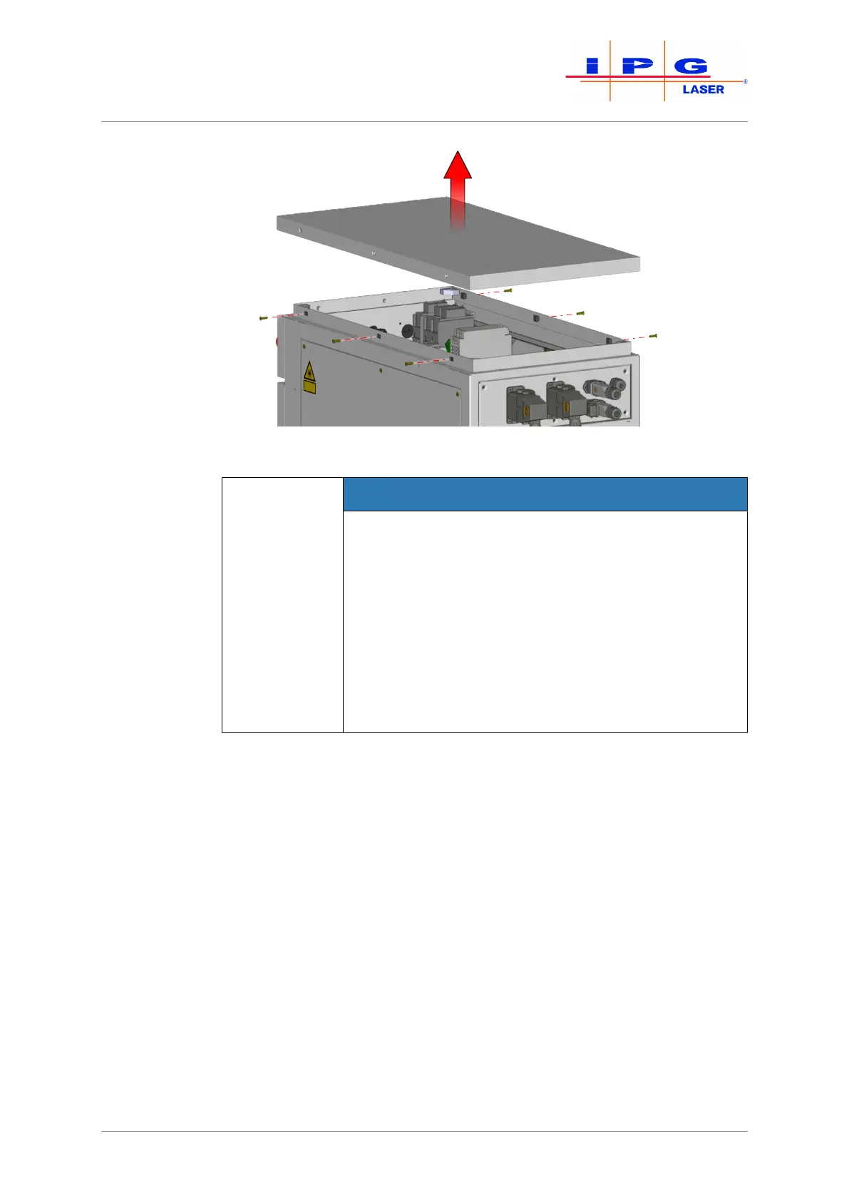
Figure18: Removing covers
NOTICE
Damage to the electronics from falling objects
The upper cover of the laser cabinet protects the un-
derlying electronics. Removing the upper cover re-
duces the protection level of the cabinet to IP00 (no
protection). The electronics of the laser can be dam-
aged by falling objects or penetrating water. This
type of damage is not covered by the warranty from
IPG.
ð Do not allow objects to fall into the laser.
ð Do not allow liquids to enter the laser.
5. Run the supply cable through the cable gland on the back side of
the product.
6. Connect the protective earth conductor PE to the green/yellow
terminal.
7. Check the rotary field (clockwise) of the supply voltage.
8. Connect the wires of the supply cable to the terminals L1, L2, L3
of the main switch in accordance with the rotary field.
9. Attach the supply cable in the interior of the housing using cable
ties to the housing frame.
10. Secure the supply cable against strain with the screw fitting.