49YLS-K
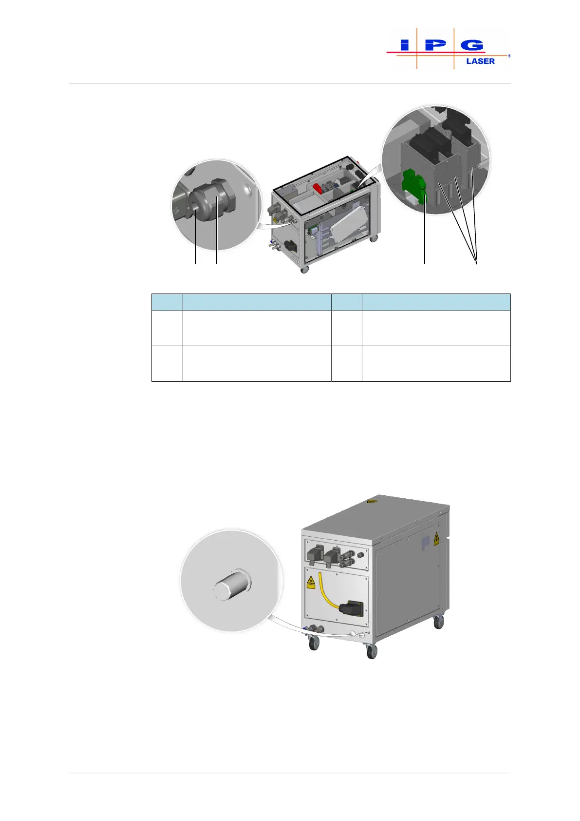
Figure19: Connection of the supply voltage
Item Designation Item Designation
1 Cable gland 3 Terminal protective earth
conductor PE
2 Screw fitting for the supply
cable
4 Terminals L1, L2, L3
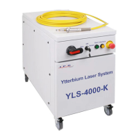
11. Reconnect the grounding line of the upper cover to the grounding
connector and screw the upper cover to the laser cabinet.
Additional earth-
ing
12. Create an additional earthing of the product at the connection
(threaded bolt M8 x 16mm) for the leakage current. The mini-
mum cross section of the earth cable must be 10 mm².
Figure20: Additional earthing connection
| Assembly and installation