.
.
Scale Link Version 3.0 installation Notes page
3
.-
L'
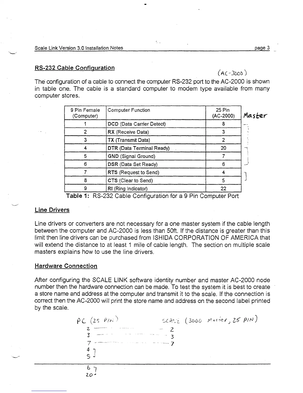
RS-232
Cabie Confiquration
The configuration of a cable to connect the computer RS-232 port to the AC-2000 is shown
in table one. The cable is a standard computer to modem type available from many
computer stores.
9
pin Female
(Computer)
1
2
3
4
5
6
I
9
(RI (Ring Indicator) 22
I
Table
1:
RS-232 Cable Configuration for a
9
Pin Computer Port
7
8
./
Line
Drivers
Computer Function
DCD (Data Carrier Detect)
RX (Receive Data)
TX (Transmit Data)
DTR
(Data Terminal Ready)
GND (Signal Ground)
DSR (Data Set Ready)
Line drivers or converters are not necessary for a one master system if the cable length
between the computer and AC-2000 is less than 50ft. If the distance is greater than this
limit then line drivers can be purchased from ISHIDA CORPORATION OF AMERICA that
will extend the distance to at least
1
mile of cable length. The section on multiple scale
masters explains how to use the line drivers.
RTS (Request to Send)
CTS (Clear to Send)
Hardware
Connection
25 Pin
(AC-2000)
8
3
2
20
7
6
After configuring the SCALE LINK software identity number and master AC-2000 node
number then the hardware connection can be made. To test the system it is best to create
a store name and address at the computer and transmit it to the scale. If the connection is
correct then the AC-2000 will print the store name and address on the second label printed
by the scale.
fla~
kGW
-.
7
!
-
4
5
1
/