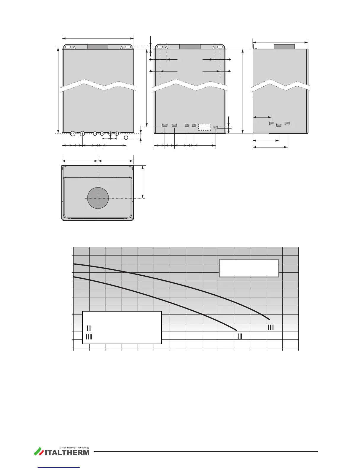
120
R
M C
300
200 200
00029_03
Ø 130
180
S
16
3545
159
136
G
F
Legend:
Gas: connecon on the boiler ¾”;
on the wall, using the oponal
original ng kit ½”
R System return (¾”)
M System ow (¾”)
C DHW outlet (½”)
F Fresh water inlet (½”)
TA/L Indicave posion for
electrical power supply and
room thermostat wirings
TA Room thermostat wiring
L Electrical power supply wiring
S Flue outlet
front view -
hydraulic connecons
on the wall
(with oponal ng kit)
upper view
front view -
hydraulic connecons
on the boiler
le side view -
hydraulic connec-
ons on the boiler
Pump capacity diagram
0
1
2
3
4
5
00023 A
00
pressure (m H
2
O)
water ow (l/h)
speed 3 of the pump
speed 2 of the pump
City Basic 24 C
The graph is referred
to the capacity available
to the system.
Air must be withdrawn from places free of pollutant (like uorine, chlorine, sulfur, ammonia, alkaline or
similar agents). In the event of installaon of the boiler in atmospheres with not negligible presence of
aggressive chemical substances (e.g. hairdressing salons, laundries) we recommend to install a type C
appliance, i.e. a forced draught and sealed chamber boiler, with air inlet from outdoor.