WH
OG
OG
GN
BK
GY
GY
BK
GN
BU
BU
YE-GN
BN
BU
YE-GN
BK
RD
RD
1
BK
N
L
42 43 44 45
5048 49 51 52
5048 49 51 52
40
41
59 60 61 62 63 64 65
7677
7879
42 43 44 45
21
22
25
24
23
28
27
26
21
22
25
24
23
28
27
26
3
2
1
6
5
4
9
8
7
10
3
2
1
6
5
4
M8
M7
S1
TF1
M11
M4
M1
M2
P1
M17
P2
TF2
M13
M5
M9
L
N
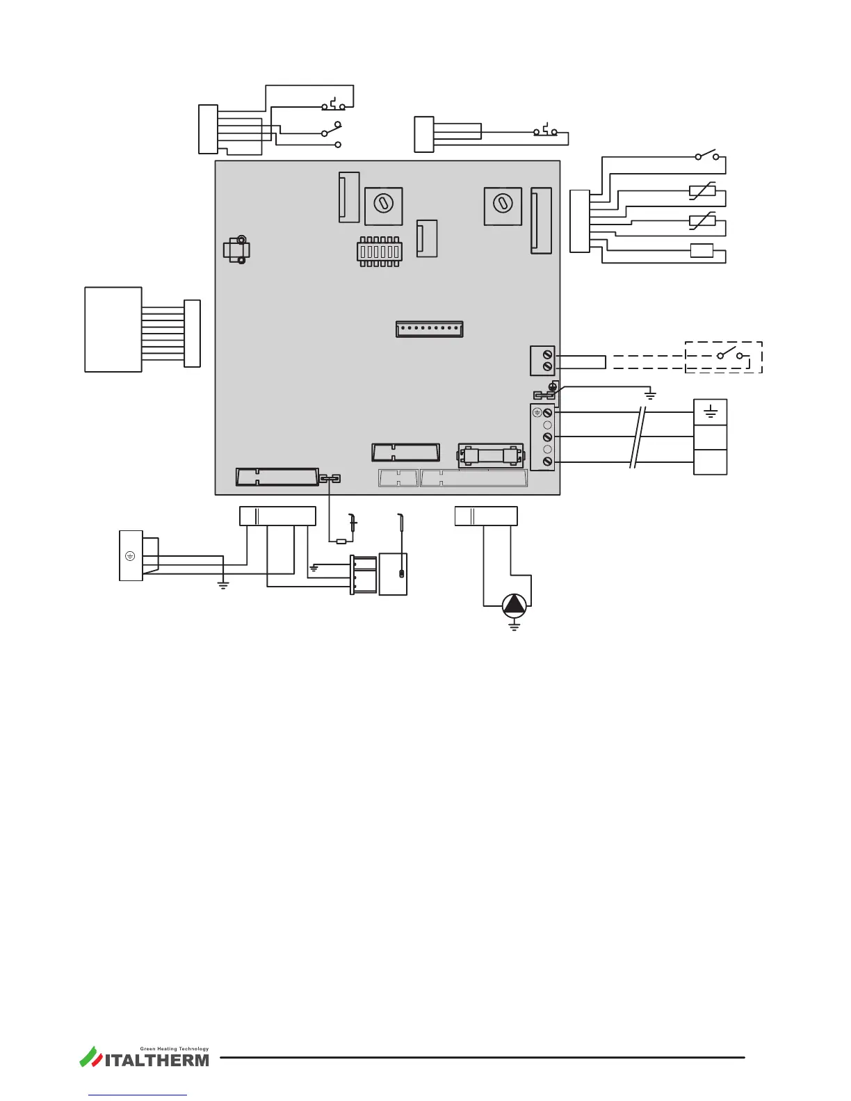
1 Flue thermostat (*)
3 Safety thermostat for
max. water temperature (*)
5 Ignion electrode
6 DHW temperature sensor
7 Flame sense electrode
8 Electronic igniter
Gas valve - modulaon control
Gas valve - opening control
13 Priority ow switch (*)
16 Loss of water pressure switch (*)
17 Pump
18 Heang circuit temperature sensor
25 Display board
27 Fuse F2A (2A fast)
Oponal external devices:
28 Room thermostat:
Voltage-free Contact for Room
Thermostat or Chronothermostat (for trade) working at
safety extra low voltage SELV. Closed contact = heang
request.
Remote control: Terminals of the original remote
control device. See also page 39. To install, remove
the jumper from the M7 terminals and connect the
device to them.
30 Connector for CH mul zones PCB kit
Abbreviaons:
Black
BN Brown
BU Blue
Green
Grey
Orange
RD Red
VT Violet
WH
White
YE Yellow
Common
Normally closed
Normally open
(*) the contacts of these components are shown in rest condions (cold condion, no system pressure, no ow)