28
Disconnect the boiler from the electrical supply. Remove the boiler cover as described in the para-
graph "Access to the inside of the boiler" on page 22.
Access the main board and switch SW1 (see also "Main board sengs" on page 27) accordingly with
the available gas type:
• OFF for
• ON for or
Ensure that the inlet gas pressure complies with the required nominal pressure (see "Technical
data" on page 34) and that the gas ow is sucient to guarantee the appliance correct work.
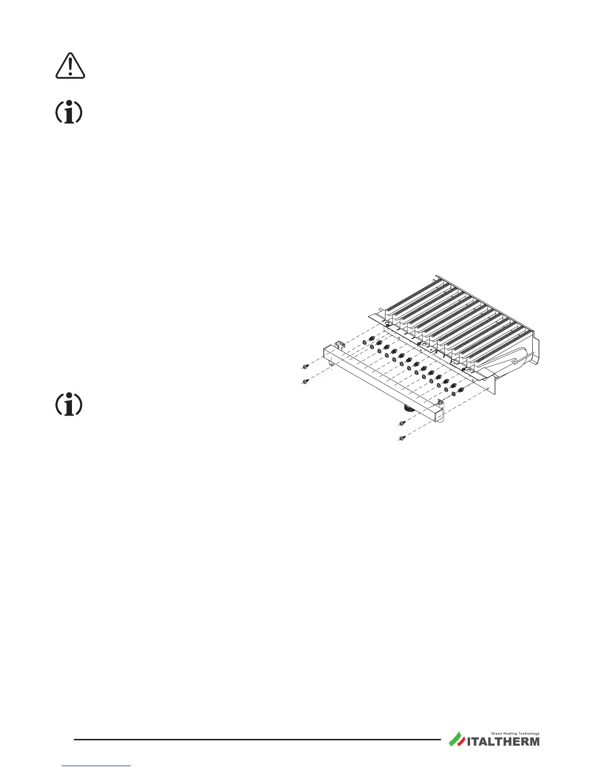
Remove the pipe between the gas valve and the injectors bar.
Remove injectors bar and replace the nozzles*
with the ones suitable for the available gas
type, using a 7 mm. spanner (see gure). The
nozzles number and diameter is stated in the
table "Technical data" on page 34.
Reassemble injectors bar and pipe, replacing
gaskets. Check, with burner ON, that there
are no gas leaks;
* Install the nozzles kit with the supplied
washers, although the exisng nozzles,
factory ed in the boiler, are originally
without washer.
Verify, with burner ignited, the inlet gas pressure (see page 23).
Check and if necessary adjust the gas valve maximum and minimum pressure (see page 23) and the
heang maximum power (see page 24).
Apply the scker indicang the type of gas (supplied with the kit) on the suitable area on “WARN-
ING” label inside the boiler.
00015 00