24
wait at least 10 seconds and verify that the measured pressure corresponds to the MAX value
indicated in the Burner Pressure table (see page 26), with regard to the boiler model and gas type;
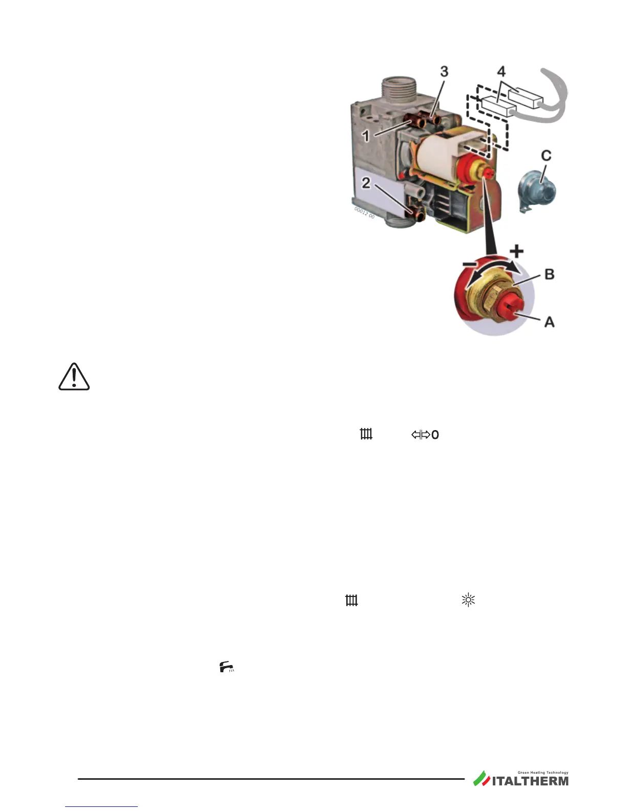
extract one of the connectors 4 that supply the
modulaon coil; verify that the measured pres-
sure corresponds to the MIN value indicated in the
Burner Pressure table (see page 26), with regard to
the boiler model and gas type;
reinsert the connector 4 ;
if it is necessary to adjust the regulaon, proceed
as it follows, referring to the gure:
• take o the protecon cap C ;
• adjust MAX pressure acng on the nut B (10 mm).
Turn clockwise to increase pressure, counterclock-
wise to decrease pressure;
• extract again one of the connectors 4 ;
• adjust MIN pressure acng on the screw A (with
a 4 mm screwdriver), paying aenon not to con-
temporarily move the nut B . Turn clockwise to
increase pressure, counterclockwise to decrease
pressure;
• reinsert the connector 4 and check that MAX pressure is not changed;
Important:
• mount the cap C ;
screw the pressure tapping point screw for gas outlet 1 and verify that there is no gas leak.
To switch the burner o, turn the Summer/Winter knob
to the posion.
The maximum heang power output must be set in accordance with the system requirements (stated
in the project). Once you know the power suitable for the heang system, refer to the "Burner pressure
tables" on page 26 and nd the burner pressure for the boiler model and for the type of gas used.
The adjustment will be performed through the boiler’s controls, following a special procedure that
avoids accidental acvaons by the User:
Loosen (2-3 turns) the screw of pressure tapping point for gas outlet 1 of the gas valve and insert
the manometer sensor. Do not use the tapping point “Vent” 3 that must always be closed;
supply the boiler and turn the Summer/Winter knob
to Summer posion ;
ensure that there are NOT domesc hot water requests (no open taps); if the room thermostat is
installed, make so that it requires the heang (e.g. raise the requested room temperature manu-
ally);
• turn the Hot Water knob
on service posion: on the display will appear a ashing number
from 00 to 99 that indicates the current set point of the value of heang power, where the value
00 corresponds to the minimum seng of the gas valve and the value 99 corresponds to the
maximum;
• wait (approximately ve seconds) that the display shows “PO” (POwer) ashing (moreover, both
the and RED indicators ash to short “pulses”).
Pressure tapping points:
1 outlet
2 inlet
3 equalizaon (VENT)
(not used in natural
draught models)