32.5
35
11
14
35
712
A A
B B
C
D
A
B
C
00005 04
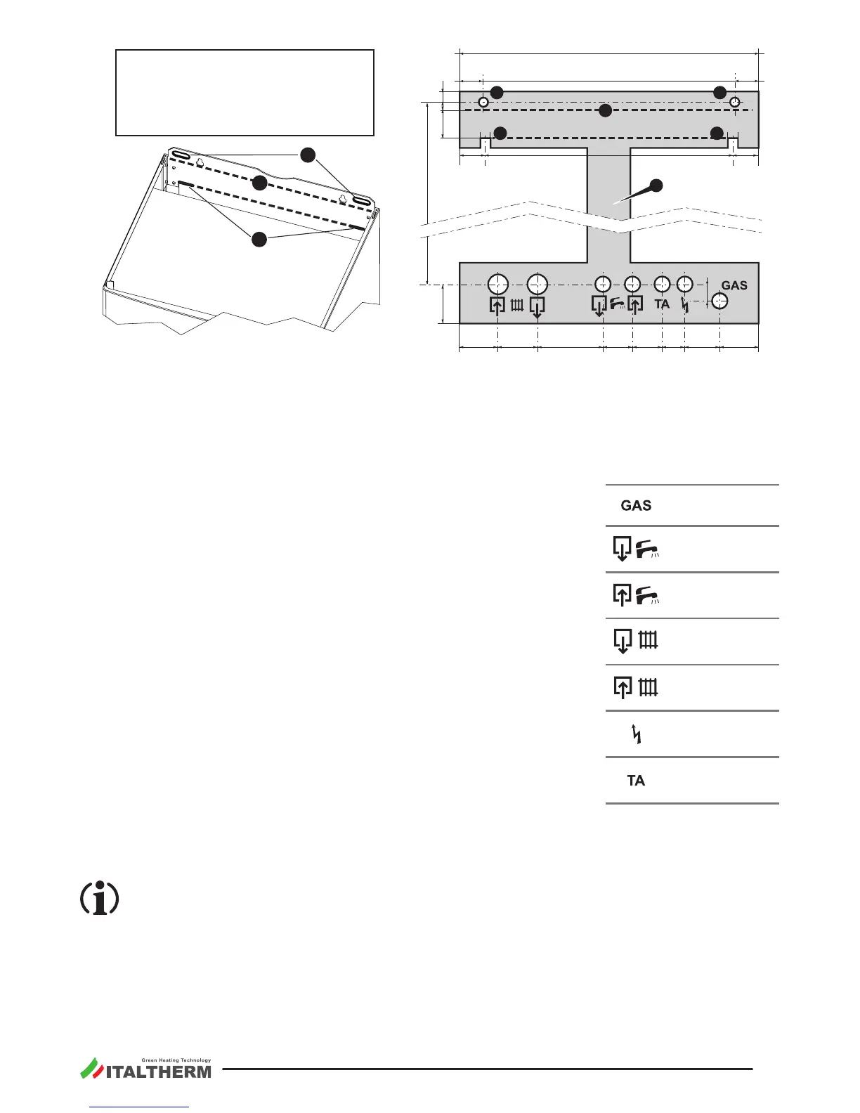
If necessary, the open hooks can be
posioned at any point along the edge B
of the boiler's frame bracket, provided
that they are 2 and that they support the
device in a correct and safe way.
Remark: A re-usable metal jig ( D in the gure) can be ordered separately, so as to facilitate connec-
ons and xing points posioning (when the original connecon kit is used). If the metal jig and/
or the original connecon kit are not used, refer to the paragraph "Dimensions and connec-
ons" on page 13 for the posion of the connecons directly on the boiler.
f Locate the exact posion of the boiler considering the sucient clearances for maintenance and
servicing: at least 50mm laterally and 300 mm on the lower side
f To x the boiler with wallplugs (“stud” type with nut), centre the rele-
vant wall holes as regards to A points. To hang it with open hooks, place
hooks in correspondence with B points.
f If the metal jig is used, hang it on the wall using the same wallplugs or
hooks and the holes or slots indicated in the gure ( A for the plugs and
B for the open hooks).
f Fix up the connecons and all ducts for heang ow and return, cold
water, hot water, gas and electrical cables, predisposing them in the
holes of the metal jig or respecng the measures in the paragraph "Di-
mensions and connecons" on page 13. The upper edge of boiler’s body
is represented by the doed line C in the gure.
f Remove the jig (if used) and hang the boiler to the wallplugs or hooks,
using the holes or slots indicated in the gure ( A for the plugs and B for
the open hooks).
f placed to close the hydraulic connecons on
the boiler.
f Proceed with the hydraulic, gas, electrical and ue connecons following the instrucons and warn-
ings reported in the following paragraphs.
The connecons of the boiler are engineered to t plain couplings with screw ring, interposing
a plain gasket of suitable size and material, that ensure a reliable seal even without excessive
ghtening force. They are NOT suitable for hemp, teon tape or similar materials
Remark: the lower grid is spare inside packing, not assembled. We suggest to x the grid only at the
end of the boiler installaon operaons.
Gas (1/2”)
Hot Water
Outlet (1/2”)
Cold Water
Inlet (1/2”)
Heang
Flow (3/4”)
Heang
Return (3/4”)
Electrical
Power Supply
Room
Thermostat