Inspection and Installation
Specification for Test Cables
Test cables are not standard accessories for the instrument. Please select op-
tional red and black test cables for individual sales based on the maximum cur-
rent value. For specifications of test cables and maximum current values, refer
to A.1 Appendix→Specifications of Red and Black Test Lines.
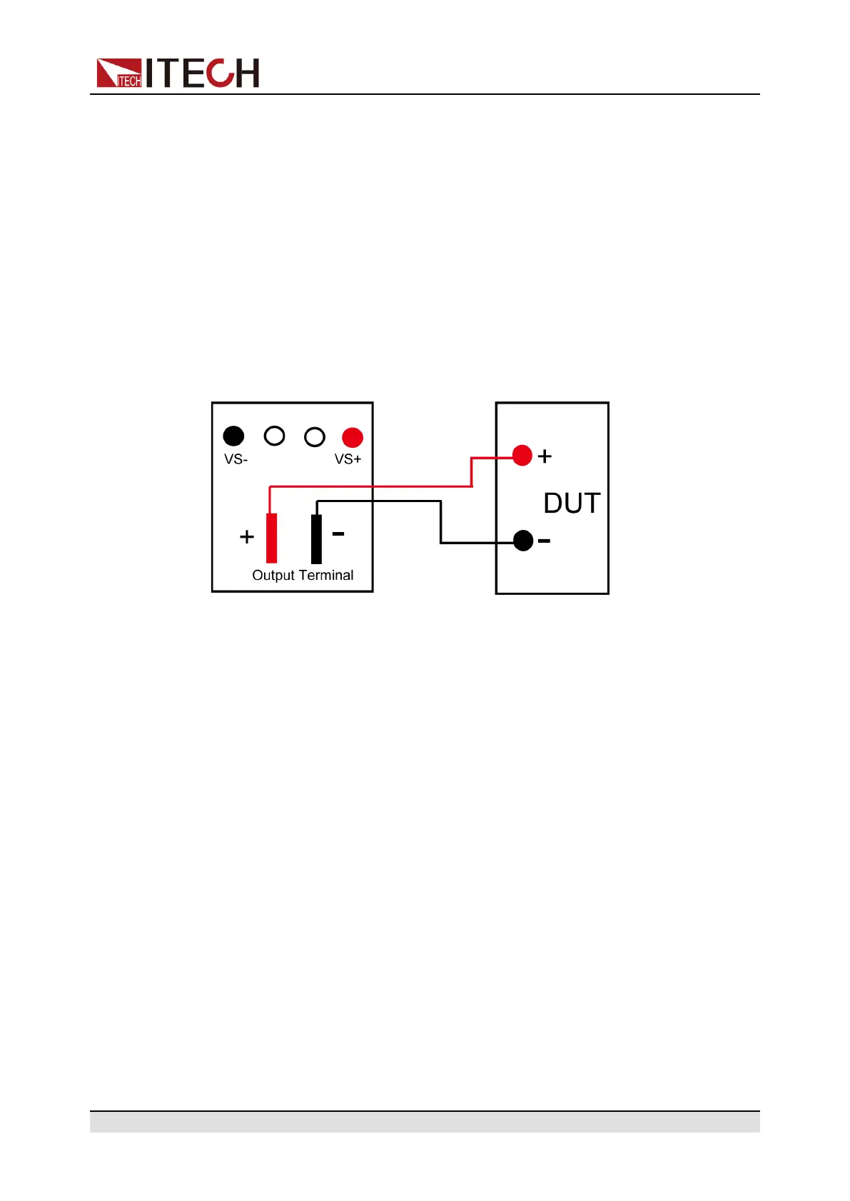
Connecting the DUT (Local Measurement)
The instrument supports two kinds of wiring methods with the DUT: local meas-
urement and remote measurement (SENSE). The default test mode is local
measurement.
The connection diagram and steps of local measurement are as follows:
1. Confirm that the power switch is in the OFF position and verify that there is
no dangerous voltage on the connection terminals.
2. Remove the output terminals cover of the power supply.
3. Loosen the screws of the output terminals and connect the red and black
test cables to the output terminals. Re-tighten the screws.
When maximum current that one test cable can withstand fails to meet the
rated current, use multiple pieces of red and black test cables. For example,
the maximum current is 1,200A, then 4 pieces of 360A red and black cables
are required.
4. Thread the red and black test cables through the output terminals cover of
the power supply and install the cover.
5. (Optional) According to the actual situation of DUT, connect the grounding
terminal on the rear panel of the instrument to the DUT to ensure the safe
grounding.
For the location information, see 1.5 Rear Panel Introduction.
6. Connect the other end of the red and black cables to the DUT. The positive
and negative poles must be properly connected and fastened when wiring.
Connecting the DUT (Remote Sensing)
Remote measurement is available for the following scenarios:
Copyright © Itech Electronic Co., Ltd.
33