Inspection and Installation
Copyright © Itech Electronic Co., Ltd. 9
2. Take off any packing materials around the mainframe.
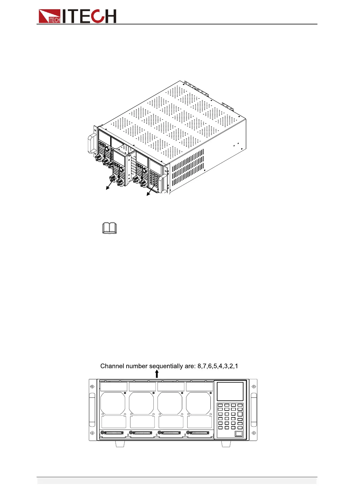
3. Push the module into the slot(as shown in figure 1-1).
4. Fix the module with a screwdriver, the position of the screw is in the upside
and backside of the machine frame.
5. Install other modules one by one
Figure 1-1 module installation
NOTE
Franklinism will damage the module. Please install the module according to standard
electrostatic prevention operation style. Avoid touching the circuit board and connectors.
1.3.1 Channel number
To IT8700, the channel number for all modules is determined by the location of
the modules in relation to right side of the mainframe. To IT8702 mainframe, the
total channel number is 8. The 1
st
& 2
nd
channel are always next to the right
mainframe while 7, 8 channels are always next to the left side. Load channel
number is fixed even if the location isn’t occupied. Load module could have one
or two channels. The channel number of single channel model from right to left
according to the slot position should be: 1
th
channel, 3
th
channel, 5
th
channel….
For module with dual channels, such as IT8722, the channel number should be:
1th and 2th channels, 3th and 4
th
channels, 5
th
and 6
th
channels… The figure
below displays the rule of the module channel number. IT8701P/IT8702P
mainframe and IT8703/IT8703P extended mainframe can be understood in the
same way.
Fig 1-2 channel number distribution
For example:If IT8702 mainframe contains two single channel modules IT8731