3. Module’s air inlet
4. Input terminal of module
3.3 VFD indicator function description
The detailed introduction of VFD’s all indicator functions are as bellow:
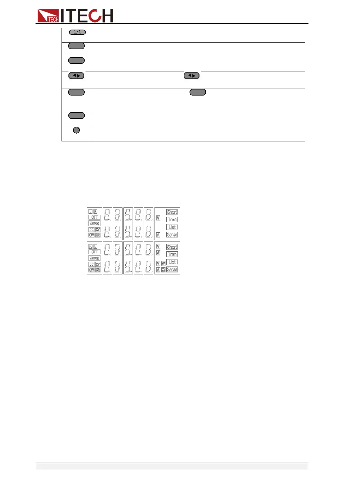
3-4 load module VFD panel
1. L/R is the indicator of dual channel module’s left/right channel, if you want
to edit left/right channel parameters, first select the cannel, L is the left
channel; R is the right channel. Single channel module will always display
R.
2. OFF indicates that the module input is off, when enable the module input,
OFF will turn off.
3. CC, CV, CR and CW are module’s 4 work modes.
4. VFD display screen has 4 lines of number show, the first line shows the
current actual voltage value, the second line shows the actual current value,
the third line shows the actual circuit’s power value, the fourth line shows
the setup value, users can set A/V/Ω/W value.
5. Short is lit up, when the module enables short-circuit function.
6. TRAN is lit up, when the module enables transient mode.
7. LIST is lit up, when select the LIST mode at the configuration.
8. SENSE is enabled in remote meter function.
3.4 8-pin control connector
IT8700 electronic load 8-pin connector on rear panel(figure 3-5):