Operations introduction
Copyright © Itech Electronic Co., Ltd. 38
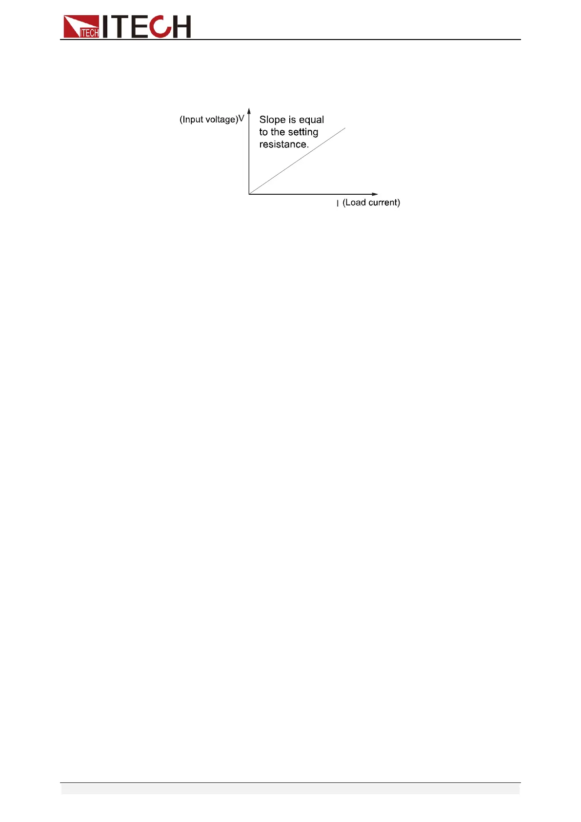
4.3.2 Constant resistance (CR) mode
In this mode, the electronic load was equivalent to a constant resistance, as
shown below; the electronic load will linearly change the current according to
the input voltage. See figure 4-2.
Fig 4-2 CR mode
Ranges
You can select the lower or higher range for CR mode too. When it shows
RANGE, you can select either of the two overlapping ranges: <LOW RANGE>
or <HIGH RANGE>. Resistance can be edited in either of the two ranges. Low
range will supply higher accuracy and better resolution when you set lower
resistance. If any value you set is outside the maximum value of the LOW
RANGE, you should select HIGH RANGE. If the electronic load work in remote
control mode(USB / RS232 / Ether-net), you can use RES:RANG command to
resistance range.
Immediate resistance level
Set the resistance level via front panel or sending command (RES <n>), if the
load is in CR mode, the new setting resistance level immediately changes the
input at a rate determined by the slew rate. If the load is not in CR mode, the
setting resistance level will be saved for use, until switch to CR mode.
Triggered voltage level
This function only can be used in remote control mode, when the load is in the
CR mode, after receive the RES:TRIG <NRF+> command, subsequent triggers
will have no effect on the input unless another triggering signal is sent. RES
command will cover the RES:TRIG <NRF+> value, this function is used to
synchronize Multi-channel input load changes.
Limited current value
Set limited current value under CR mode.
Transient resistance level
Set A/B transient resistance level on front panel or by remote operation, the
load can continuously toggle between the two levels when transient operation is
turned on.
4.3.3 Constant voltage (CV) mode
In this mode, the electronic load will attempt to sink enough current to control
the source voltage to the programmed value. See figure 4-3.