Appendix F Grounding Specifications
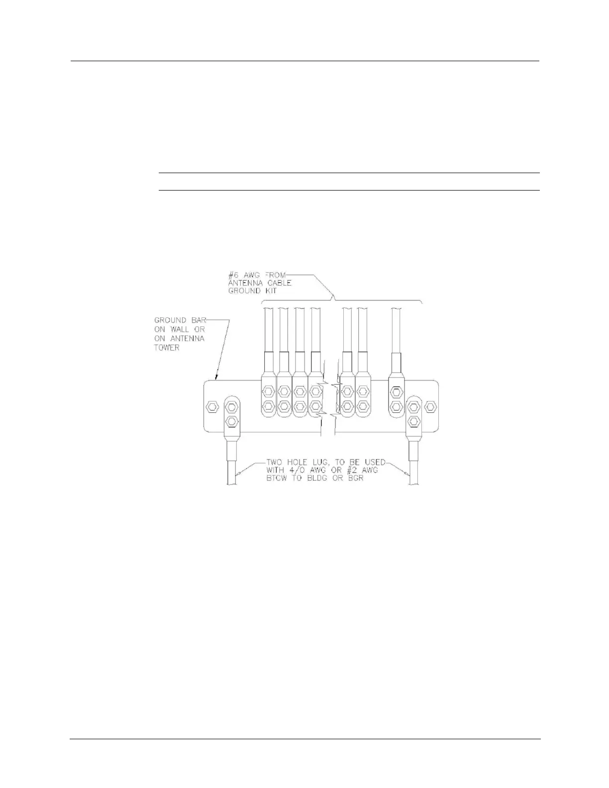
• Ground bars. Bars must be 1/4 inch thick solid electrical grade copper and must be
electroplated with tin 0.0003 inches thick typical, 0.0002 inches thick minimum. Hole
spacing between top row and center row holes must be ¾ inch, between center row
and bottom row holes must be 1 inch (Telco), and between top row and bottom row
must be 1 ¾ inch (NEMA). Connect ground lugs as shown in Figure 2-1. Ground lugs
on opposite sides of the ground bar may share holes in the ground bar if connected
properly.
Warning Never mount lugs on top of each other on a ground bar.
• Exothermic Welding. Exothermic welds must be Cadweld, a registered trademark
of Erico Products, Inc. of Cleveland, Ohio, or ThermOweld, a division of Continental
Industries, Inc. of Tulsa Oklahoma or equivalent.
The following illustration shows the installation of ground wire to ground bar.
• Ground Clamp. Used for conduit or water pipe, for instance. Burndy GAR style UL
clamp with two- hole provisions for long barrel multiple crimp two-hole lugs or
equivalent.
Conduit. Conduit requirements vary due to state and local construction codes. The
local engineering firm determines what is required depending on the site type and
jurisdiction. Consider material and labor costs when selecting a conduit type as long
as all applicable codes are followed.
• Metal conduit. (At a minimum) UL listed galvanized rigid steel conduit
(minimum size: 1-1/2-inch trade size) with UL listed fittings. Steel compression
fittings, watertight fittings, and bonding to grounding conductors at both ends are
required. Do not use set screw settings.
98 TDC-0971-011 CCU 100 and Repeater 100 Installation Guide
Proprietary and Confidential
 Loading...