Installing 40W and 50W ERT Modules
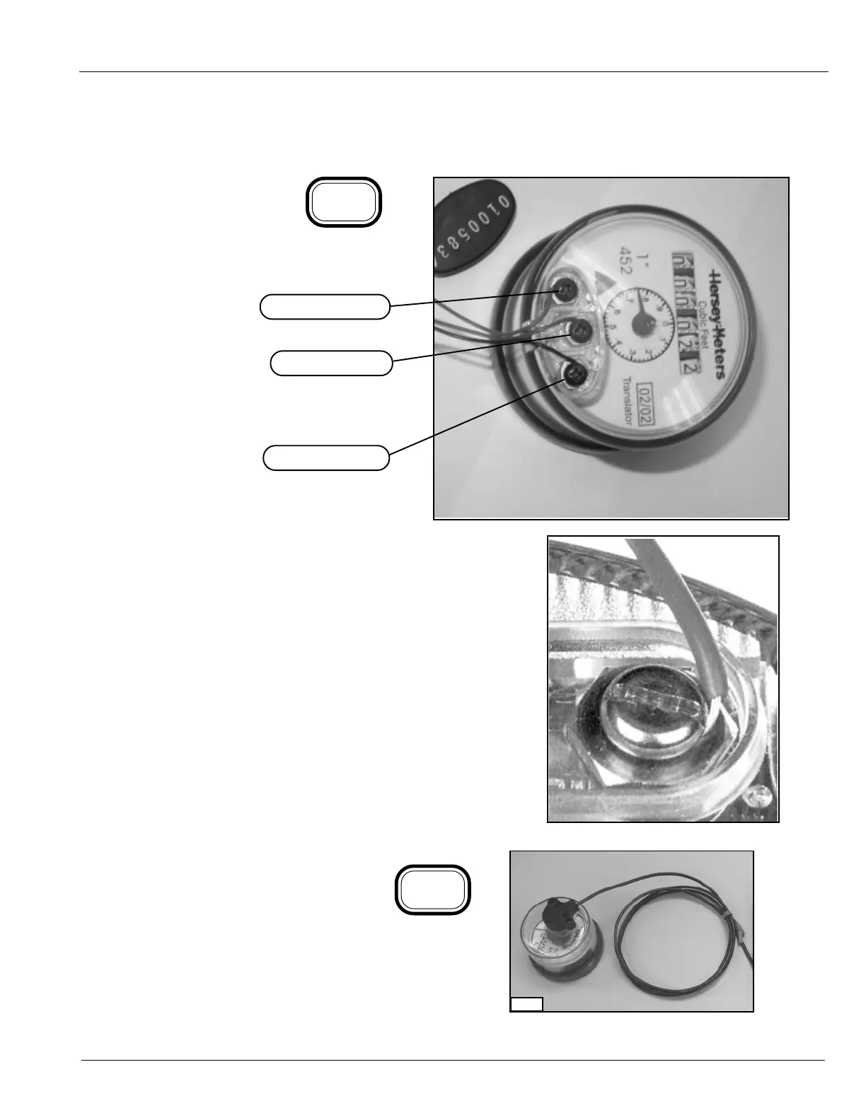
TO CONNECT TO HERSEY TRANSLATOR REGISTER:
Remove the screw terminal
cover from the register. Install
the red wire under
this screw head.
Tighten the screw fully.
Install the green wire
under this screw head.
Tighten the
screw fully.
Install the black wire under
this screw head.
Tighten the screw fully.
Install the screw terminal cover.
6-4
IMPORTANT
6-3
Be sure to install the wires around the screws in a
clockwise direction, as shown. If you don’t, the wires
may partially or completely come out from under the
screw heads as you tighten them. Also, make sure
no insulation is compressed under the screw head,
or the wire might not make good contact.
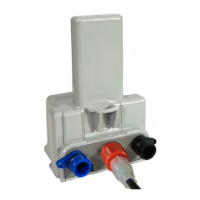
To assemble the ER pickup assembly follow the
instructions furnished with the meter register.
Refer to section 6.14 to connect the cable to the
ERT module.
6-5
01873