Installing 40W and 50W ERT Modules PUB-0126-001 4/04
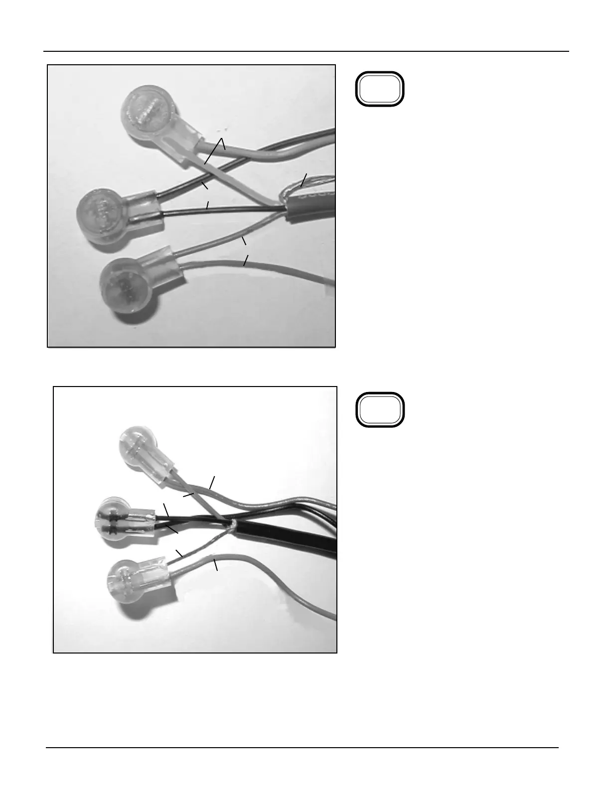
To connect a 40W or 50W ERT module
to a Badger register with a brown-insu-
lated cable, connect as follows:
• Red to red
• Green to green
• Black to black
• Fold the unused bare wire backward
along the brown cable, as shown.
This configuration supports the cut cable
feature (Badger register equipped with a
black-insulated cable does not support
cut cable).
NOTE: The 40W must have 3 wires to
support the cut cable feature.
6-10
6-6
Brown
G
R
Bare
B
B
Black
G
R
Bare
B
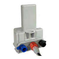
To connect a 40W or 50W ERT
module to a Hersey ER register
connect as follows:
• Red to black
• Bare to green
• Black to red
6-11
R
NOTE: For instructions on how to
connect gelcap connectors, see
Appendix A.