EasyManua.ls Logo

ITRON SL7000 - Auxiliary and Communication Wiring

ITRON SL7000
125 pages
Print Icon
To Next Page IconTo Next Page
To Previous Page IconTo Previous Page
Loading...
SL7000 User Guide
B
201
Upper fixing point (2) to lower fixing points (centre to centre)
C
150
Left to right lower fixing points (centre to centre)
D
252
Upper fixing point (1) centre to lower edge of meter body
E
4
Lower edge of meter body to lower edge of short terminal cover
E
58
Lower edge of meter body to lower edge of standard terminal cover
E
93
Lower edge of meter body to lower edge of long terminal cover
All dimensions are in millimetres.
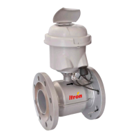
9.5. Auxiliary and communication wiring
Auxiliary wiring for Full IO Board
Terminal
Function
Terminal
Function
Terminal
Function
20
Control output 1
29
Pulse output 1
36
Pulse input 1
21
Control output 2
30
Pulse output 2
37
Pulse input 2
22
Control output 3
31
Pulse output 3
38
Pulse input 3
23
Control output 4
32
Pulse output 4
39
Pulse input 4
33
Pulse output 5
40
PI Common
25
CO Common
34
Pulse output 6
26
Control input 1
35
PO Common
27
Control input 2
28
CI Common
The control output and input terminal blocks accept cables up to 2.5mm².
The pulse output and input terminal blocks accept cables up to 1.5mm².
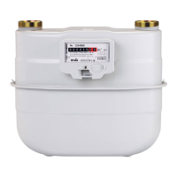
Auxiliary wiring for Light IO Board
Terminal
Function
Terminal
Function
Terminal
Function
22
Control output 1
33
Pulse output 1
38
Pulse input 1
23
Control output 2
34
Pulse output 2
39
Pulse input 2
25
CO Common
35
PO Common
40
PI Common
27
Control input 1

Table of Contents

Related product manuals