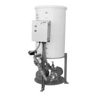
Figure 11: Side view of an incorrect vertical alignment
4. Repeat the previous steps until the permitted reading value is achieved.
Perform angular alignment for a horizontal correction
1. Set the angular alignment indicator (A) to zero on left side of the driver coupling half (Y), 90° from
the top-center position (9 o’clock).
2. Rotate the indicator through the top-center position to the right side, 180° from the start position
(3 o’clock).
3. Record the indicator reading.
When the reading value is... Then...
Negative The coupling halves are farther apart on the right side than
the left. Perform one of these steps:
• Slide the shaft end of the driver to the left.
• Slide the opposite end to the right.
Positive The coupling halves are closer together on the right side
than the left. Perform one of these steps:
• Slide the shaft end of the driver to the right.
• Slide the opposite end to the left.
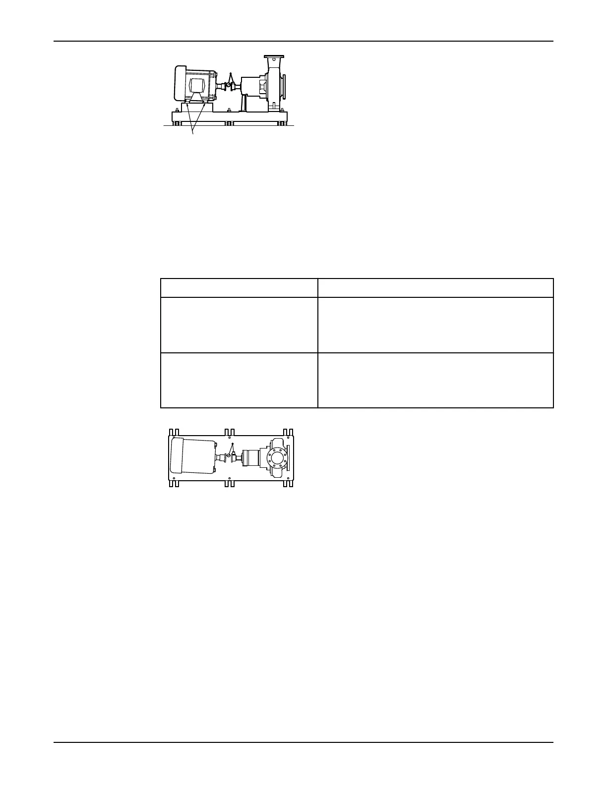
Figure 12: Top view of an incorrect horizontal alignment
4. Repeat the previous steps until the permitted reading value is achieved.
Perform parallel alignment for a vertical correction
Before you start this procedure, make sure that the dial indicators are correctly set up.
A unit is in parallel alignment when the parallel indicator (P) does not vary by more than 0.002 in.
(0.05 mm) as measured at four points 90° apart at the operating temperature.
1. Set the parallel alignment indicator (P) to zero at the top-center position (12 o’clock) of the driver
coupling half (Y).
2. Rotate the indicator to the bottom-center position (6 o’clock).
3. Record the indicator reading.
Installation
30 Model 3196 i-FRAME Installation, Operation, and Maintenance Manual