When the reading
value is...
Then...
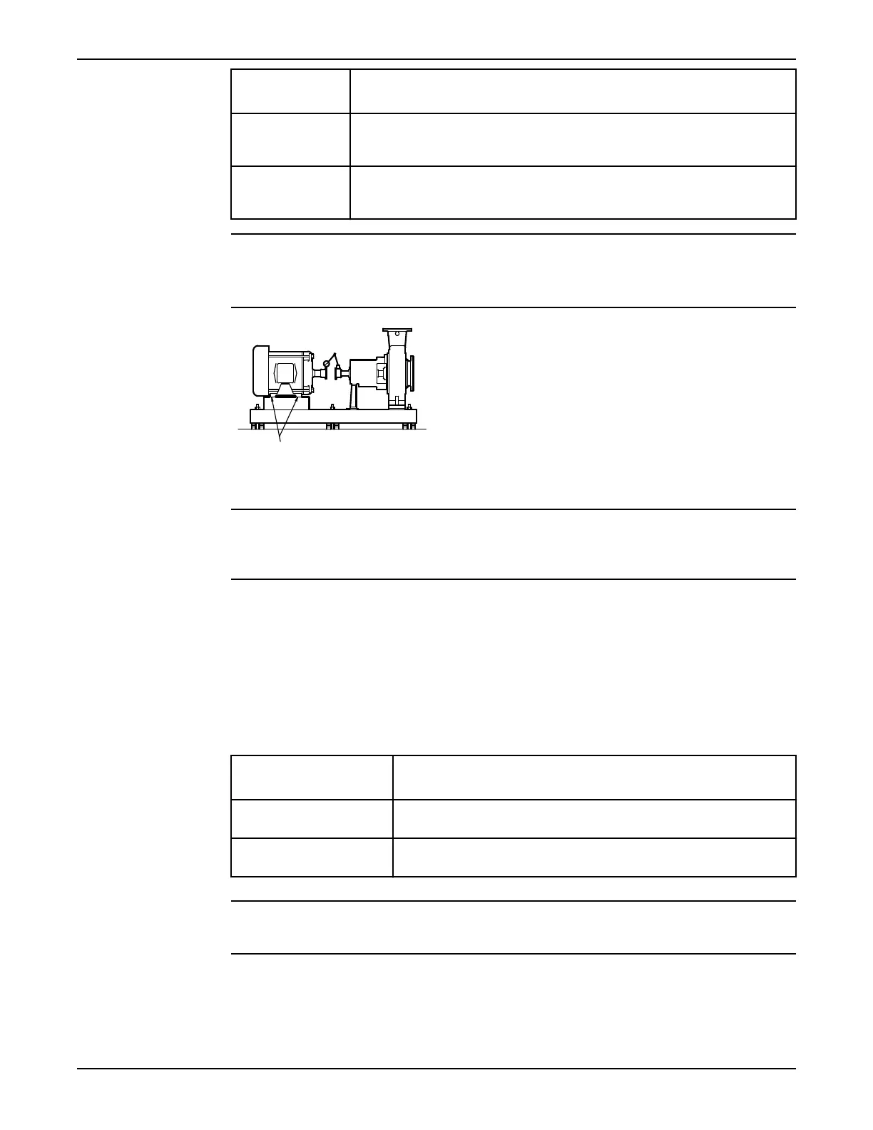
Negative The pump coupling half (X) is lower than the driver coupling half (Y). Remove
shims of a thickness equal to half of the indicator reading value under each
driver foot.
Positive The pump coupling half (X) is higher than the driver coupling half (Y). Add
shims of a thickness equal to half of the indicator reading value to each driver
foot.
NOTICE:
You must use an equal amount of shims with each driver foot to prevent misalignment. Failure to do
so can result in equipment damage or decreased performance.
Figure 13: Side view of an incorrect vertical alignment
4. Repeat the previous steps until the permitted reading value is achieved.
NOTICE: The specified permitted reading values are valid only at operating temperature. For cold
settings, other values are permitted. You must use the correct tolerances. Failure to do so can result in
misalignment and reduced pump reliability.
Perform parallel alignment for a horizontal correction
A unit is in parallel alignment when the parallel indicator (P) does not vary by more than 0.002 in.
(0.05 mm) as measured at four points 90° apart at the operating temperature.
1. Set the parallel alignment indicator (P) to zero on the left side of the driver coupling half (Y), 90°
from the top-center position (9 o’clock).
2. Rotate the indicator through the top-center position to the right side, 180° from the start position
(3 o’clock).
3. Record the indicator reading.
When the reading value
is...
Then...
Negative The driver coupling half (Y) is to the left of the pump coupling half
(X).
Positive The driver coupling half (Y) is to the right of the pump coupling half
(X).
4. Slide the driver carefully in the appropriate direction.
NOTICE: Make sure to slide the driver evenly. Failure to do so can negatively affect horizontal
angular correction.
Installation
Model 3196 i-FRAME Installation, Operation, and Maintenance Manual 31