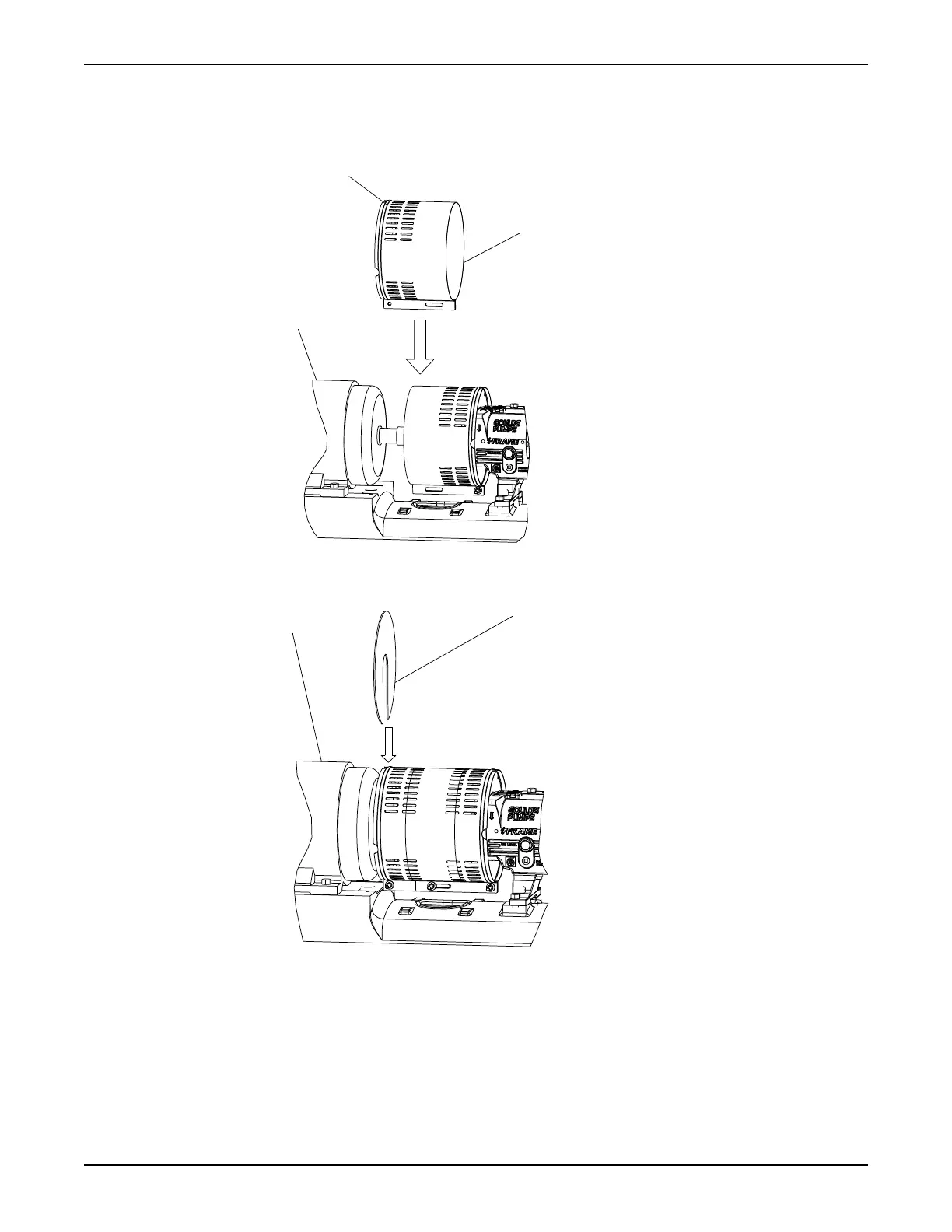
b) Place the driver half of the coupling guard over the pump half of the coupling guard.
The annular groove in the coupling guard half must face the motor.
Annular
Driver
Guard half
groove
6. Place the driver-side end plate over the motor shaft.
7. Place the driver-side end plate in the annular groove of the driver-half of the coupling guard.
8. Use a bolt, a nut, and two washers to secure the coupling guard half to the end plate. Hand-tighten
only.
The hole is located on the driver-side of the coupling guard half.
9. Slide the driver-half of the coupling guard towards the motor so that the coupling guard completely
covers the shafts and coupling.
Commissioning, Startup, Operation, and Shutdown
Model 3196 i-FRAME Installation, Operation, and Maintenance Manual 49
 Loading...