8
IVT 495 TWIN 9518799
23
22
21
20
19
18
17
16
15
14
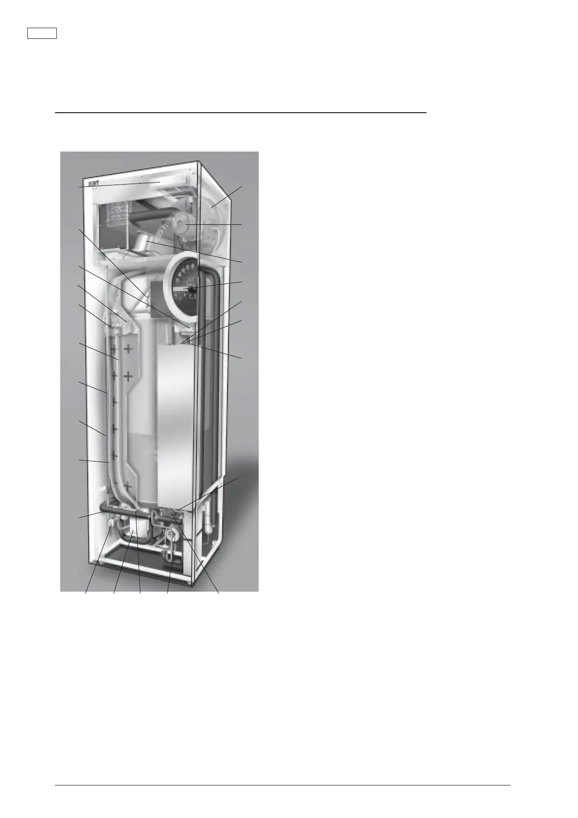
Connecting area
1. Expansion vessel for the heating system
2. Circulation pump, heat transfer fluid/ground
coil
3. Exhaust air fan
4. Display
5. Miniature circuit breaker (MCB)
6. Manual operation switch, normally in off
position
7. Main switch. The plant is on when the
switch is set at 1 and off when it is set at 0
8. Overheat protection electric element, reset
on the underside of the electric box
9. Shunt valve
10. Circulation pump for the heating system
11. Safety valve for tap water
12. Waste water vessel
13. Pressure gauge for the heating system
Should normally be set at 0.5 – 1.5 bar
14. Filling tap for the heating system
15. Condensed water hose
16. Cold water
17. Hot water
18. Waste water hose
19. Safety valve for the heating system
20. Venting nipple for the heating system
21. Anode control unit
22. Anode
23. Exhaust air filter
13 12 11 10 9
1
2
3
4
5
6
7
8
From the inside
USER
 Loading...


