EasyManuals Logo

Jackson TEMPSTAR User Manual

Jackson TEMPSTAR
103 pages
To Next Page IconTo Next Page
To Previous Page IconTo Previous Page
Page #32 background imageLoading...
Page #32 background image
Tempstar LT/NB/S/SDS Technical Manual 7610-011-86-35
Issued: 12-07-2007 Revised: N/A
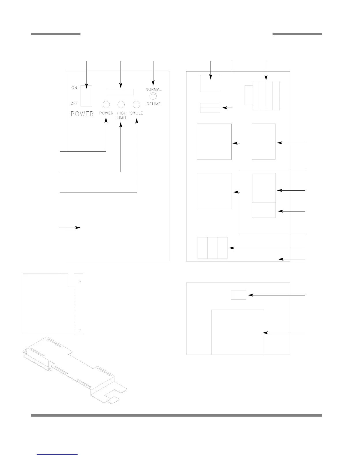
SECTION 5: PARTS SECTION
SIDE MOUNTED CONTROL BOX ASSEMBLY
24
1
2, 21
3
CONTROL BOX FRONT COVER
4
5
6
7, 8
INNER CONTROL BOX LAYOUT
9, 22
11, 22
10, 22
12, 22
13, 14
12, 22
15, 16
17
18, 23, 24
19
CONTROL BOX BOTTOM LAYOUT
21, 22
20
The mounting screws for the control box front cover (10-32 X
1/2” Slotted Truss Head Screws) may be ordered using Mfg.
No.: 05305-011-39-85.
Bracket, Side Mount Electrical Box
05700-041-65-68
Cover, Dielectric Control Panel
05700-021-50-89

Table of Contents

Other manuals for Jackson TEMPSTAR

Questions and Answers:

Question and Answer IconNeed help?

Do you have a question about the Jackson TEMPSTAR and is the answer not in the manual?

Jackson TEMPSTAR Specifications

General IconGeneral
ModelTEMPSTAR
CategoryDishwasher
WeightVaries by model
Depth25-5/8"
Height33-1/2"

Related product manuals