SERVICE MANUAL FOR SXG323&326
144
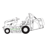
j. Inspection of the IC regulator
5.5. RE-ASSEMBLY
Re-assemble in reverse order of disassembly, fol-
lowing the next precautions.
a. Pressing in the bearings
Press in the bearing with a hand press carefully
to avoid slanted installation.
At room temperature, it is very hard to press in
the bearing due to interference. So it is recom-
mendable to heat up the whole frame at about
100°C.
Note:
When installing the bearing, use ajig which is
designed to press only the outer race. Support the
frame at the bearing box not at the stay.
• Connect the removed 1C regulator, variable DC
power supply, voltmeter, and a lamp as illustrat-
ed. (Keep SW1 and SW2 turned off.)
• Set the power supply at 12V.
• Turn on SW1. Make sure that LI (in place of the
charge lamp) is lit bright and L2 (in place of the
rotor coil) is also lit.
• Then turn on SW2 with SW1 on. Make sure that
LI is turned off and L2 remains lit.
• When the power supply output is changed gradu-
ally from 12V until 14.5±0.6 at about 25°C
with both SW1 and SW2 turned on, L2 should
turn off and LI should remain turned off.
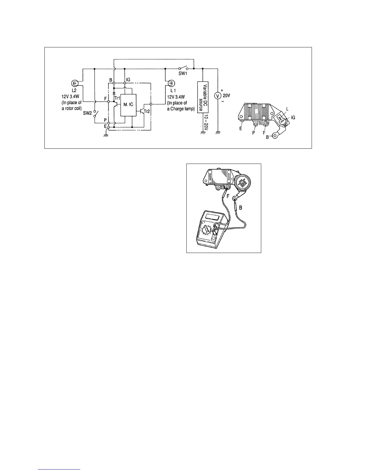
After above test, check the diode between ter-
minal B and F.
• Set the tester at KQ range and check for conti-
nuity across terminals B and F. Check by chang-
ing the polarity of the tester. There should be
continuity in one direction and no continuity in
the other direction.
Fig. 13-68
Fig. 13-67
 Loading...