CHAPTER 4. ENGINE
61
4
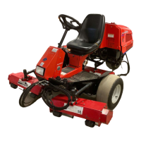
(4) Then install bearing cap seals (B). Drive them in
until they subside 0 - 0.3 mm (0 - 0.012 in.) from
the cylinder block end. Fill the gaps with sili-
cone compound. Tighten the journal bearing cap
to the specified torque.
Fig. 4-95
3.3.7. INSTALLATION OF PISTON/CON-NECT-
ING-ROD ASSEMBLIES
•Install bearings on the connecting-rod big end
and bearing cap with the bearing projections
seated securely in respective notches in the big
end and bearing cap. Apply engine oil to the
bearing surfaces.
•Clean the cylinder bores and crankshaft, and
apply engine oil to them.
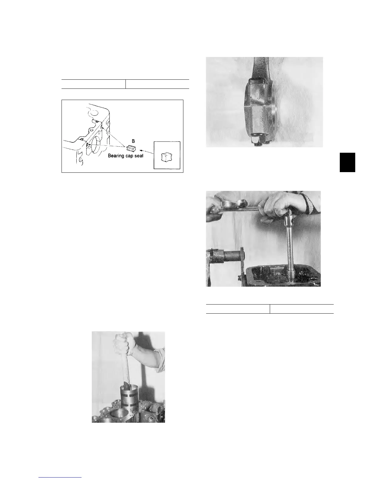
• Set the crankshaft at BDC.
• Turn the front mark on the piston head towards
the front and make sure that the piston ring gaps
are 120°apart from each other. Then insert the
piston/connecting rod assembly, compressing the
piston rings with a piston ring compressor, into
the cylinder until the connecting rod bearing
comes into contact with the crankpin.
Fig.4-96
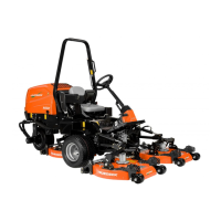
• Install the connecting rod bearing cap having the
same number that the connecting rod has.
Fig. 4-97
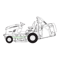
•Tighten the connecting rod bearing cap to the
specified torque.
Fig. 4-98
The crankshaft should turn smoothly.
Specified torque:
4.5 - 5.5 kgf・m
Specified torque:
2.7 - 3.3 kgf・m
 Loading...