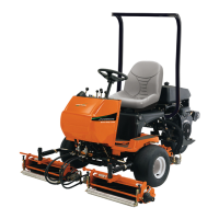
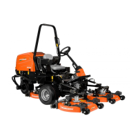
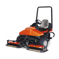
SERVICE MANUAL FOR SXG323&326
6
CHAPTER 4. ENGINE ....................................................................................................................33
1. ENGINE ...................................................................................................................................33
1.1. SPECIFICATIONS ............................................................................................................33
1.2. PERFORMANCE CURVES ..............................................................................................34
2. INSPECTION AND ADJUSTMENT ..........................................................................................35
2.1. INSPECTION OF ENGINE OIL ........................................................................................35
2.2. INSPECTION OF FAN BELT ............................................................................................35
2.3. INSPECTION AND ADJUSTMENT OF VALVE CLEARANCES .......................................36
2.3.1. Remove the cylinder head cover. ...............................................................................36
2.3.2. Turn the crankshaft by hand so that the piston in No.1 cylinder reaches at
TDC: align the TDC notch in the crankshaft pulley with the pro-jection on the
gear case. ...................................................................................................................36
2.3.3. Insert a feeler gauge of a specified thickness and adjust the clearance with
the adjusting screw......................................................................................................36
2.4. INSPECTION AND ADJUSTMENT OF NOZZLE OPENING PRESSURE AND
INJECTION TIMING ..........................................................................................................36
2.4.1. Adjustment of the valve opening pressure of the injection nozzles. ...........................36
2.4.2. Inspection of oil tightness of valve seats ....................................................................37
2.4.3. Spraying condition of injection nozzle .........................................................................37
2.4.4. Inspection and adjustment of injection timing .............................................................37
2.5. COMPRESSION AND UNLOADED IDLING SPEEDS .....................................................39
2.5.1. Inspection of compression ..........................................................................................39
2.5.2. Inspection and adjustment of the idling speeds ..........................................................39
2.6. INSPECTION OF WATER PUMP .....................................................................................39
2.6.1. Inspection of the pump and pulley ..............................................................................39
2.6.2. Inspection of the bearing unit ......................................................................................40
2.7. INSPECTION OF THERMOSTAT .....................................................................................40
3. ENGINE BODY ........................................................................................................................40
3.1. CYLINDER HEAD .............................................................................................................40
3.1.1. REMOVAL OF THE CYLINDER HEAD ......................................................................41
3.1.2. DISASSEMBLY ...........................................................................................................42
3.1.3. INSPECTION ..............................................................................................................42
3.1.4. DISASSEMBLY AND INSPECTION OF THE ROCKER ARM SHAFT .......................45
3.1.5. INSPECTION OF THE PUSH RODS .........................................................................46
3.1.6. INSTALLATION OF THE CYLINDER HEAD...............................................................46
3.2. GEAR CASE .....................................................................................................................48
3.2.1. EXPLODED VIEW ......................................................................................................48
3.2.2. REMOVAL OF THE GEAR CASE ...............................................................................48
3.2.3. RE-INSTALLATION OF THE GEAR CASE.................................................................49
3.3. CYLINDER BLOCK ..........................................................................................................50
3.3.1. EXPLODED VIEW ......................................................................................................50
3.3.2. DISASSEMBLY OF THE CYLINDER BLOCK ............................................................51
 Loading...

