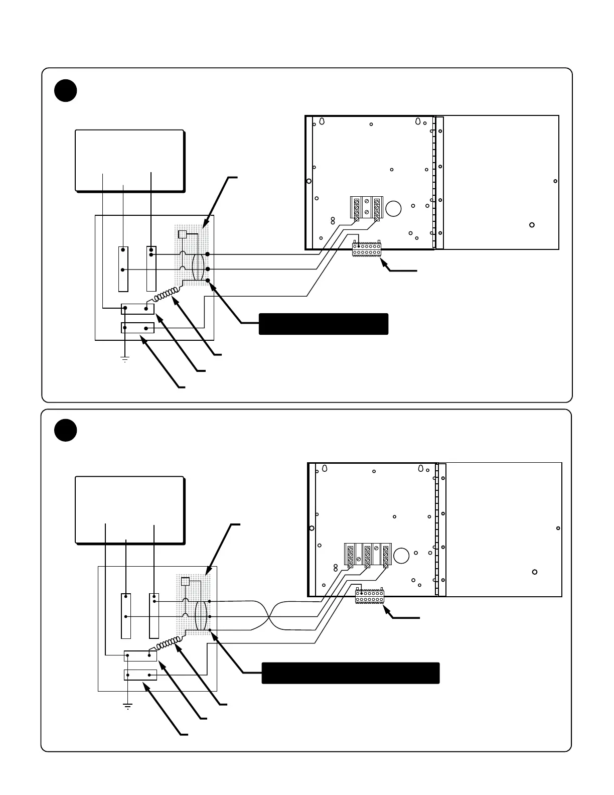
Red
Pigtail
Neutral Bus
Ground
TB2
TB1
Black
Green
Main
Service
Panel
with
GFCI
Hot Tub
Load Box
2-Pole
GFCI
Breaker
Ground
2-Pole Circuit Breaker with 2-Wire Grounded Load Connection
(3 Wires to Hot Tub, 2-Hot, 1-Ground)
Red
Pigtail
Neutral Bus
Ground
TB2
TB1
Black
White
Green
Main
Service
Panel
with
GFCI
Hot Tub
Load Box
White
Black
Red
240 VAC/120 VAC
White
Black
Red
240 VAC
2-Pole
GFCI
Breaker
Ground
Load Neutral Lug on Breaker
2-Pole Circuit Breaker with 3-Wire Grounded Load Connection
(4 Wires to Hot Tub, 2-Hot, 1-Neutral, 1-Ground)
A
B
No Load Neutral Wire
Note: service disconnect not
shown in this diagram.
Note: service disconnect not
shown in this diagram.
W B
B
R
R
 Loading...