50
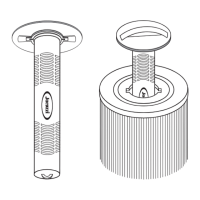
A15 Flow Switch Illustration
Flow Switch #6560-852
• J315, J-325 Models
Connection: This ow switch style has spade connectors at top for easy cable removal for
electronic troubleshooting.
Flow Switch #2560-040
• 2014+ J300 (except J-315 and J-325)
Connection: This ow switch style has cable with curled nger connectors that can be re-
moved from plug for electronic troubleshooting.
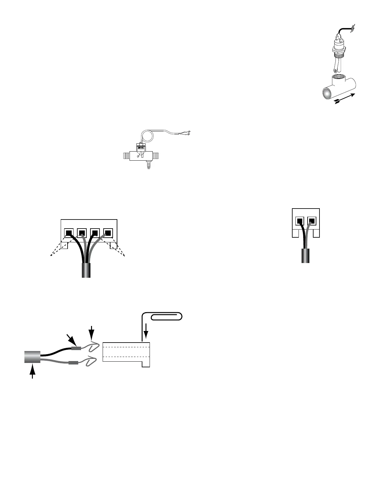
A16 Sensor Harness Diagram
• Flow Switch
To remove a sensor/switch wire from the either J2 or J3
connectors, insert the end of a paper clip into the slot cor-
responding with the wire to be removed. This will depress
the tine on the pin allowing the wire to be pulled from the
harness.
IMPORTANT!
When reinstalling the sensor/switch, make sure the tine on
the pin is lifted so the sensor wire will lock into the connector
body.
Hi-limit
Sensor wires
Temperature
Sensor wires
J3 Connector (Cable Side)
Shown while Plugged into Circuit Board
J2 Connector (Cable Side)
Shown while Plugged into Circuit Board
Connector
(Side View)
TINE
Hi-limit Sensor, Temperature Sensor,
Flow Switch Wires
PIN
Paper Clip
Hi-limit
Sensor wires
Temperature
Sensor wires
J3 Connector (Cable Side)
Shown while Plugged into Circuit Board
J2 Connector (Cable Side)
Shown while Plugged into Circuit Board
Connector
(Side View)
TINE
Hi-limit Sensor, Temperature Sensor,
Flow Switch Wires
PIN
Paper Clip
Hi-limit
Sensor wires
Temperature
Sensor wires
J3 Connector (Cable Side)
Shown while Plugged into Circuit Board
J2 Connector (Cable Side)
Shown while Plugged into Circuit Board
Connector
(Side View)
TINE
Hi-limit Sensor, Temperature Sensor,
Flow Switch Wires
PIN
Paper Clip
6560-852
2560-040
 Loading...