Page 15
ENGLISH
Jandy
®
Variable-Speed Pumps
|
Installation & Operation Manual
3.5.5 Aqualink TCX
Aqualink TCX supports a single variable-speed pump.
Dip Switches 3-4 must always be set in the OFF position
when the pump is connected to a TCX Automation
System. This is true even when connected to a TCX
system using the automation pass-through wiring on a
Jandy SpeedSet controller.
3.5.6 All Other Jandy Automation Systems
All other Jandy automation systems support up to 4
variable-speed pumps utilizing Dip Switches 3-4 in the
same manner as dened in section 3.5.3.
3.6 Auxiliary Relay Operation
Pumps models in this manual are equipped with a
terminal bar that provides user access to two built-
in Auxiliary Relays. The normally-open relays are
activated under certain operating conditions and are
intended to be used to control external devices that
require system water ow for proper functioning, such as
booster pumps, salt water chlorinators, etc.
See Figures 12-13 for compartment details and location
of the auxiliary relays and wiring illustrations.
Auxiliary Load Connection Requirements
WARNING
ELECTRICAL SHOCK HAZARD
Due to the potential risk of fire, electric shock, or injuries
to persons, Jandy
®
Pumps and any auxiliary loads must
be installed in accordance with the National Electrical
Code
®
(NEC
®
), all local electrical and safety codes, and
the Occupational Safety and Health Act (OSHA). Copies
of the NEC may be ordered from the National Protection
Association, 1 Batterymarch Park, Quincy, MA 02169, or
from your local government inspection agency.
In Canada, Jandy
Pumps must be installed in accordance
with the Canadian Electrical Code (CEC).
• The Auxiliary Load relay contacts are rated at
230V/115V, 11A RMS. Please ensure the requirements
of the equipment to be connected to the Auxiliary Load
do not exceed this rating.
3.6.1 Auxiliary Relay Operation
Auxiliary Relay contact activation is speed dependent.
Auxiliary Relay 1 has an activation speed of 1725 RPM
and Auxiliary Relay 2 has an activation speed of 2250
RPM.
The Jandy SpeedSet controller provides the ability
to reprogram the Auxiliary Relay open/close speeds
for customization. Open/close speed settings that are
changed using this feature are permanent even if the
SpeedSet controller is disconnected.
Please refer to the "Settings" section in the Jandy
SpeedSet controller I/O manual for additional details.
3.6.2 Contact Closure
From a stopped condition, there is a three-minute delay
before the Auxiliary Relay contact is closed when the
motor speed reaches and maintains the activation speed.
Once the three minute run time criteria has been reached,
when going from an RPM below the activation speed to
an RPM above the activation speed, there is a 5-second
delay before the Auxiliary Relay contact is closed.
3.6.3 Contact Opening
When going from an RPM above the activation speed to
an RPM below the activation speed, the relay opening is
always immediate.
Section 4. Dry Contact Operation
External relays or switches can be used with the dry
contacts if a Zodiac controller is not connected to the
RS-485 line. By creating a circuit that runs between the
dry contact, the external switch/relay, and the common
on the dry contact, when the circuit is closed the pump
will turn on, prime at 2750 RPM for 3 minutes, and go to
the pre-determined speed of the dry contact indenitely
until the circuit is opened by the external relay.
If no inputs are jumped to common, the RPM is zero.
When any Zodiac controller is connected through
RS-485, all dry contact commands will be ignored. Refer
to Figures 12 and 13 for dry contact wiring. Refer to
table 5 for dry contact speed settings.
4.6.1 Dry Contact Speed Settings
Dry contact speed settings were adjusted with motor
serial numbers beginning with the letter B.
1. Please refer to the motor rating label to nd the
motor serial number.
2. Refer to table 5 to determine the dry contact speeds
for the motor.
Dry Contact Speeds Are Based
On Motor Serial Numbers
Dry
Contact
Serial # Begins
with "A"
Serial # Begins
with "B" or Later
1 3000 RPM 3450 RPM
2 1400 RPM 1375 RPM
3 2200 RPM 2600 RPM
4 1725 RPM 1750 RPM
Table 5. Dry Contact Speed Settings
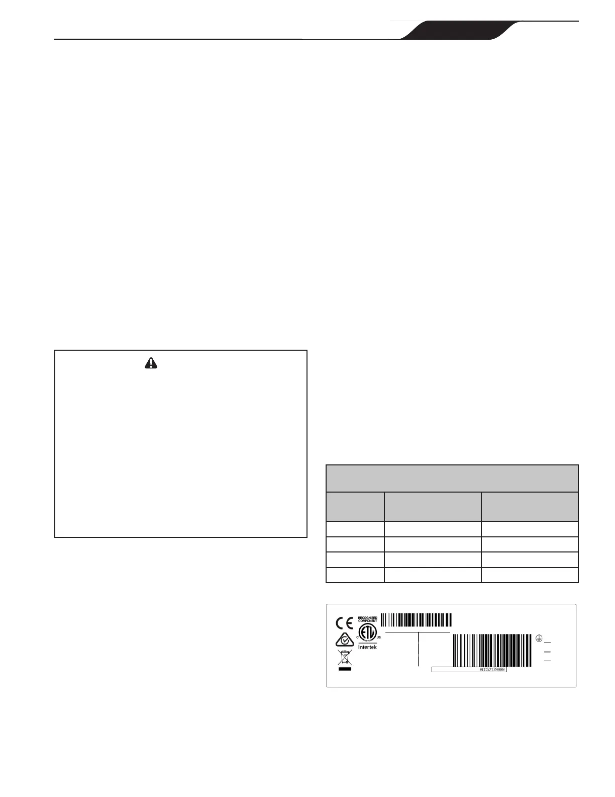
(G)
GROUND
EARTH
(L2/N)
(L1)
USE COPPER
CONDUCTORS
ONLY
ACCEPTABLE
FOR FIELD
WIRING
LINE 2
NEUTRAL
LINE 1
ENCL: TEFC
ROT
: CWLE
FR
: 56
Electronically Protected
INSUL: CLASS F IPX5
AMB: 50 C
DUTY: CONT
ZODIAC POOL SYSTEMS LLC, www.zodiac.com
MOTOR SERIAL NO:
50 HZ
60 HZ
1 PHASE
1 PHASE
230 VAC
230 / 115 VAC
1.85 THP
1.85 THP MAX
8 A 8 / 16 A
P1: 1.70 kW
P2: 1.38 kW
RPM: 600 - 3450
SF: 1.00
SF: 1.00
5009595
Conforms to ANSI/UL
STD 1004-1, 1004-7,
Cer�fied to CSA STD
C22.2 No. 100 & 77
UL 1081, CSA C22.2 108 – Pool Pump Duty
B0245802
H0662700 REV G
Figure 11. Motor Rating Plate Label

 Loading...