20
UMG 96RM
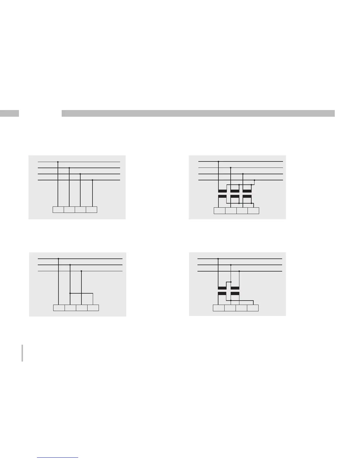
Connection diagram, voltage measurement
L1
L2
L3
N
V1 V2 V3 VN
• 3p 4w (addr. 509= 0), factory setting
L1
L2
L3
N
V1 V2 V3 VN
• 3p 4wu (addr. 509 = 1)
• 3p 4u (addr. 509 = 2)
L1
L2
L3
V1 V2 V3 VN
L1
L2
L3
V1 V2 V3 VN
• 3p 2u (addr. 509 = 5)
Fig. System with three-phase conductors and a
neutral conductor.
Fig. System with three-phase conductors and
a neutral conductor. Measurement via voltage
transformer.
Fig. System with three-phase conductors and
no neutral conductor. Measured values that re-
quire a neutral refer to a calculated neutral.
Fig. System with three-phase conductors and
no neutral conductor. Measurement via voltage
transformer. Measured values that require a
neutral refer to a calculated neutral.

 Loading...