67
UMG 96RM
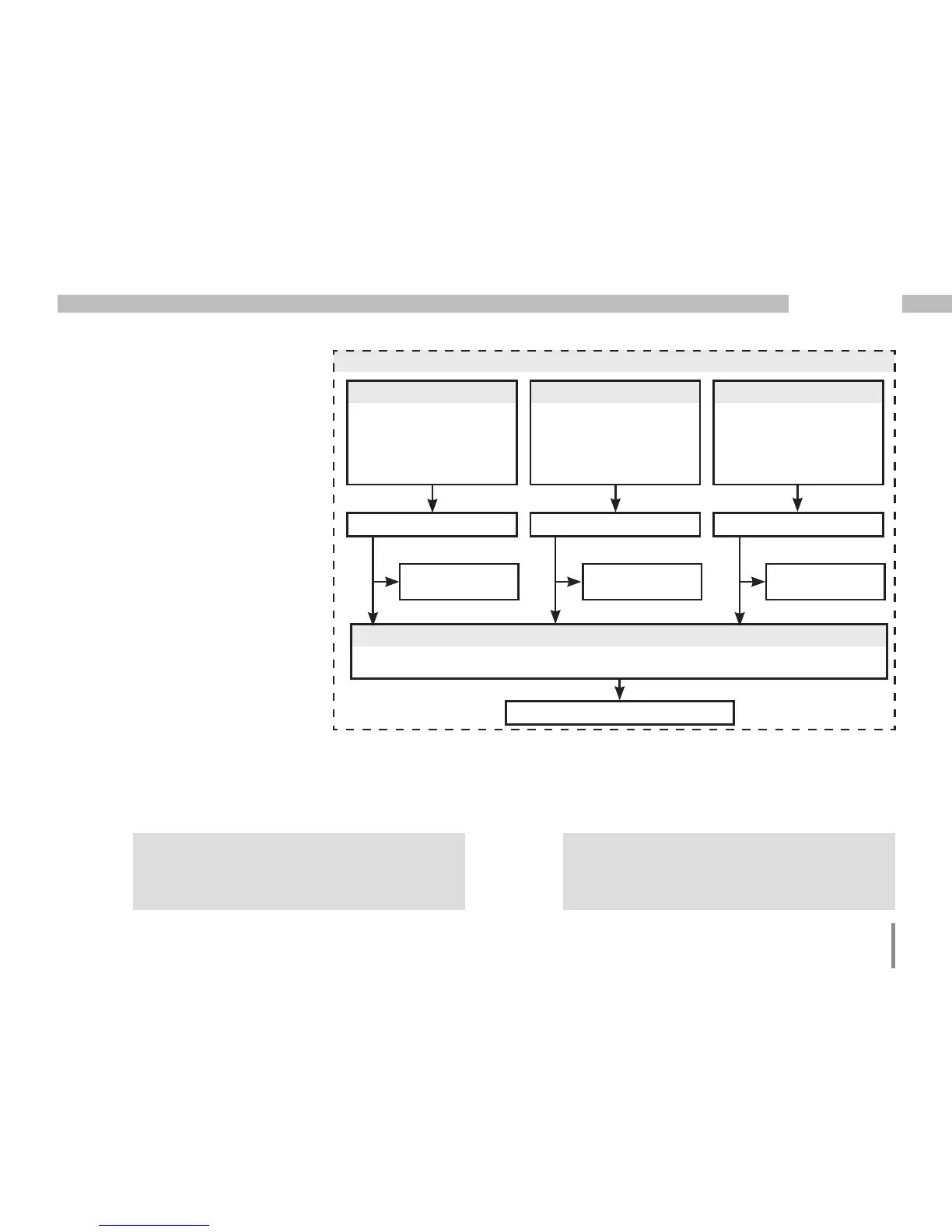
Comparator
Two comparator groups, each with
3 comparators, are available for
monitoring limit values. The results
from comparators A, B and C can
be AND or OR linked.
The linkage result from comparator
group 1 can be assigned to digital
output 1 and the linkage result from
comparator group 2 is assigned
to digital output 2.
Only 3-digit parameter addresses can be
entered in the UMG 96RM.
4-digit parameter addresses can be entered
in the GridVis.
C
We recommend making settings for limit
value monitoring via the GridVis.
C
Measured value (addr. 110)
Limit value (addr. 108)
Minimum turn-on time (addr. 111)
Lead time (addr. 112)
Operator ">=", "<" (addr. 113)
Comparator A
Measured value (addr. 116)
Limit value (addr. 114)
Minimum turn-on time (addr. 117)
Lead time (addr. 118)
Operator ">=", "<" (addr. 119)
Comparator B
Measured value (addr. 122)
Limit value (addr. 120)
Minimum turn-on time (addr. 123)
Lead time (addr. 124)
Operator ">=", "<" (addr. 125)
Comparator C
Comparator result (addr. 610) Comparator result (addr. 611) Comparator result (addr. 612)
Total running time
(addr. 5078)
Total running time
(addr. 5080)
Total running time
(addr. 5082)
Link the results from comparators A, B and C
Link the results from comparators A, B and C as AND or OR (addr. 107).
Comparator group 1
Linkage result (addr. 616)

 Loading...