31
UMG 96RM
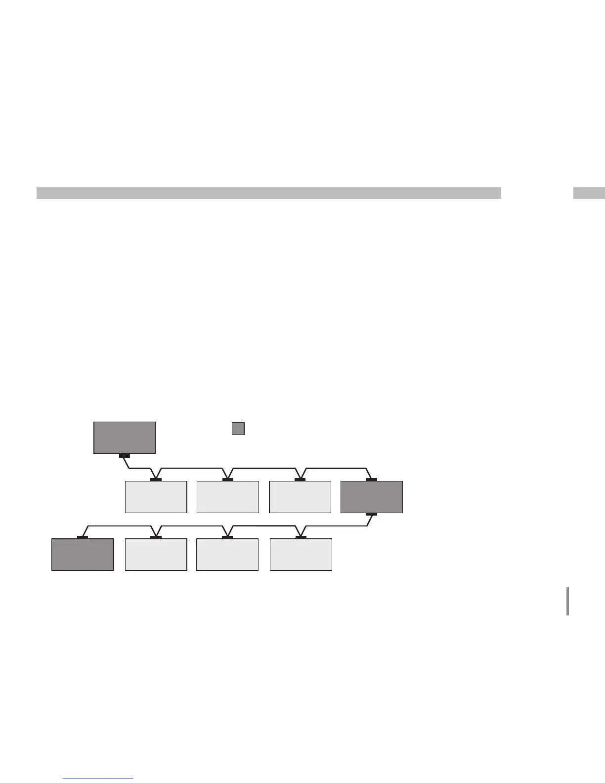
Bus structure
• All devices are connected in a bus structure (line) and
each device has its own address within the bus (also
see programming parameters).
• Up to 32 stations can be interconnected in one
segment.
• The cable is terminated with resistors (bus termination,
120 ohm 1/4 W) at the beginning and end of a segment.
• If there are more than 32 stations, repeaters (line
amplifiers) must be used in order to connect
the individual segments.
• Devices with activated bus termination must
be supplied with power.
• It is recommended to set the master at the end
of a segment.
• The bus is inoperative if the master is replaced with
an activated bus termination.
• The bus can become unstable if the slave is replaced
with an activated bus termination or is dead.
• Devices that are not involved in the bus termination
can be exchanged without making the bus unstable.
SlaveSlaveSlave
Slave Slave Slave Repeater
Slave Slave Slave Slave
Master
Power supply necessary
Bus terminator on
T
T
T
T
Fig. Diagram of bus structure

 Loading...