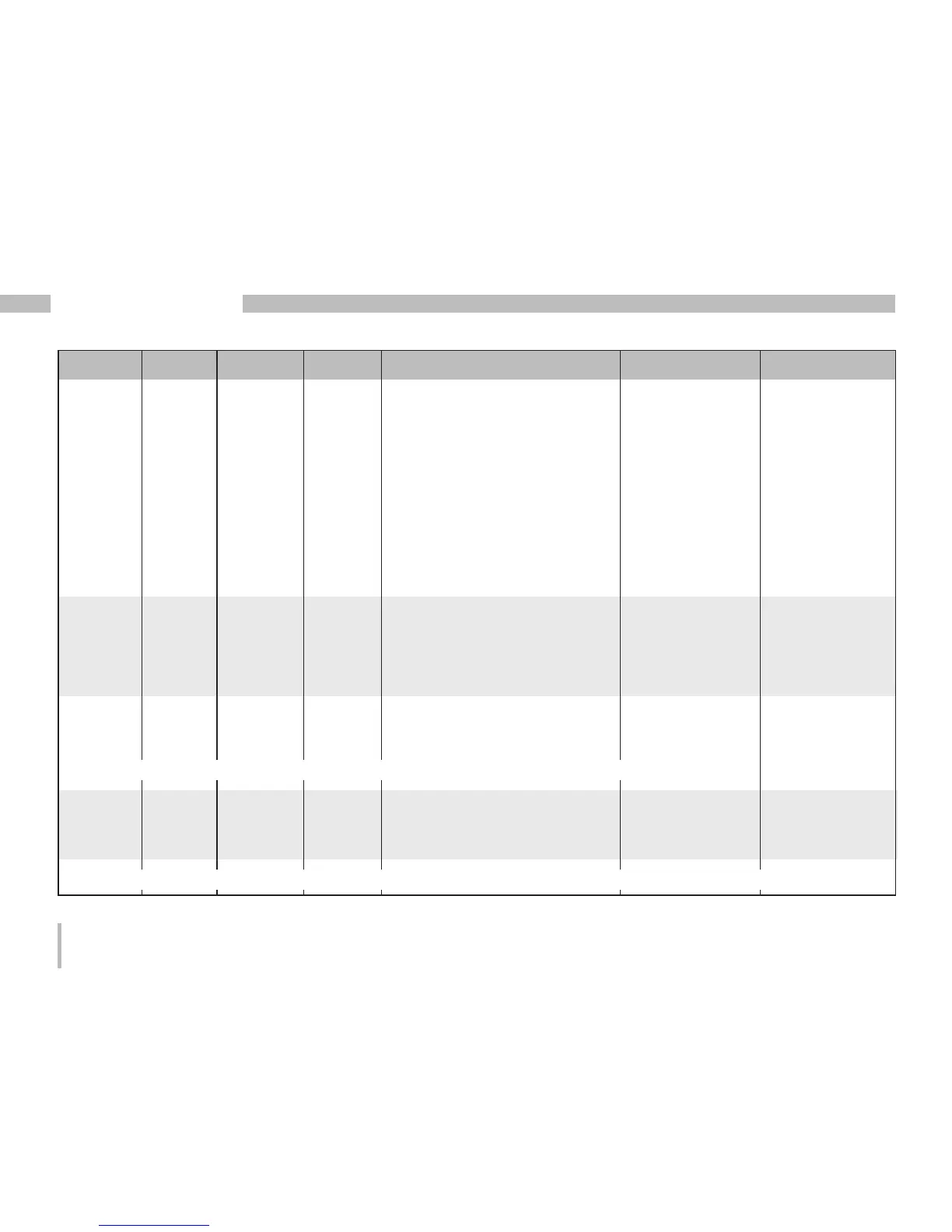
Address Format RD/WR Unit Note Adjustment Range Default
50 SHORT RD/WR - Password 0 .. 999 0 (no password)
100 SHORT RD/WR - Address of the measured value,
Digital output 1 0..32000 874
101 SHORT RD/WR - Address of the measured value,
Digital output 2 0..32000 882
102 FLOAT RD/WR Wh Pulse value,
Digital output 1 -1000000..+1000000 1000
104 FLOAT RD/WR Wh Pulse value,
Digital output 2 -1000000..+1000000 1000
106 SHORT RD/WR 10ms Minimum pulse length (1=10 ms)
Digital output 1/2 1..1000 5 (=50 ms)
500 SHORT RD/WR - Terminal assignment, I L1 -3..0..+3 +1
501 SHORT RD/WR - Terminal assignment, I L2 -3..0..+3 +2
502 SHORT RD/WR - Terminal assignment, I L3 -3..0..+3 +3
503 SHORT RD/WR - Terminal assignment, U L1 0..3 1
504 SHORT RD/WR - Terminal assignment, U L2 0..3 2
505 SHORT RD/WR - Terminal assignment, U L3 0..3 3
506 SHORT RD/WR - Clear min. and max. values 0..1 0
507 SHORT RD/WR - Clear energy meter 0..1 0
508 SHORT RD/WR - Force write EEPROM. 0..1 0
Note: Energy values and minimum and maximum values are written to the EEPROM every 5 minutes.
509 SHORT RD/WR - Voltage connection diagram 0..7 0
510 SHORT RD/WR - Current connection diagram 0..8 0
511 SHORT RD/WR - Relative voltage for
THD and FFT 0, 1 0
The voltages for THD and FFT can be shown on the display as L-N or L-L values. 0=LN, 1=LL
 Loading...