JCB EcoMAX Engine Installation Manual
Page 54 of 64 320/A9164-1 © JCB Power Systems Ltd.
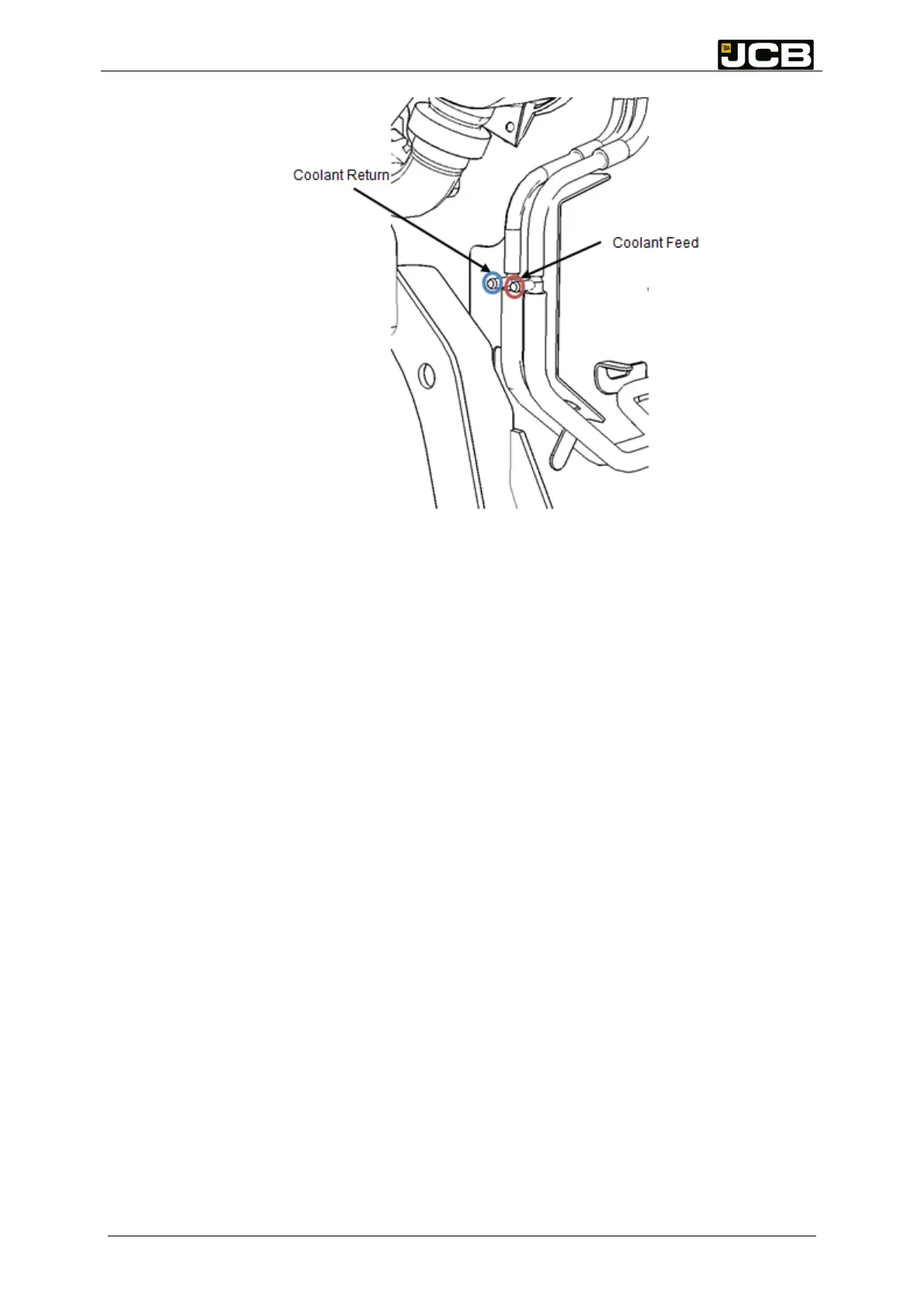
Figure 17: Engine side coolant connection barbs
The hose barbs on the engine side of the cooling system shown in Figure 17 are suitable for
the 3/8
th
coolant hoses supplied. The hoses should be clamped with worm drive clamps or
crimp style clamps.
Hoses are supplied with the Industrial Power Units complete with SAE J2044 connections to
fit the tank module coolant connections. The engine end can be shortened by the installer to
suit the particular installation if required but the line length must not be increased or joined/
broken into otherwise the de-frost performance of the system and consequently the
legislative compliance may be compromised
Routing of the hoses should avoid proximity to hot surfaces.