4. ADJUSTMENTS
The table below indicates the theoretical cutting length for possible combinations of
the above sprocket wheels:
Fig. 4.8 for pick-up (Standard)
24 blades A1 A2 A3 B C
5.7 mm. 18 14 30 30 14
7.2 mm. 18 14 30 30 18
*8.5 mm. 21 14 36 25 18
10.0 mm. 21 14 36 30 25
12.0 mm. 36 18 36 25 25
14.3 mm. 36 18 25 30
*16.6 mm. 36 18 18 25
*Standard cutting length
REPLACEMENT AND ADJUSTMENT OF BLADES
When replacing a single blade the blade must be placed at the same distance from
the shearbar as the other blades. To ensure that the rotor is in balance it may be
necessary to replace the opposite blade as a used blade has a different weight
compared to a new blade.
Even if there is no visible damage to the blade bolts, they should always be replaced
together with the blades as they might have been overloaded.
CAUTION: Check the distance between the blade and the shearbar (0.5
mm) with the supplied gauge before and after the bolts are
tightened.
WARNING: Only use original blade bolts when replacing. Tighten the blade
bolts with a torque wrench to 400 Nm (approx. 40 kpm) or with
the supplied spanner using approx. 40 kg leverage (400 Nm).
PR11-0232
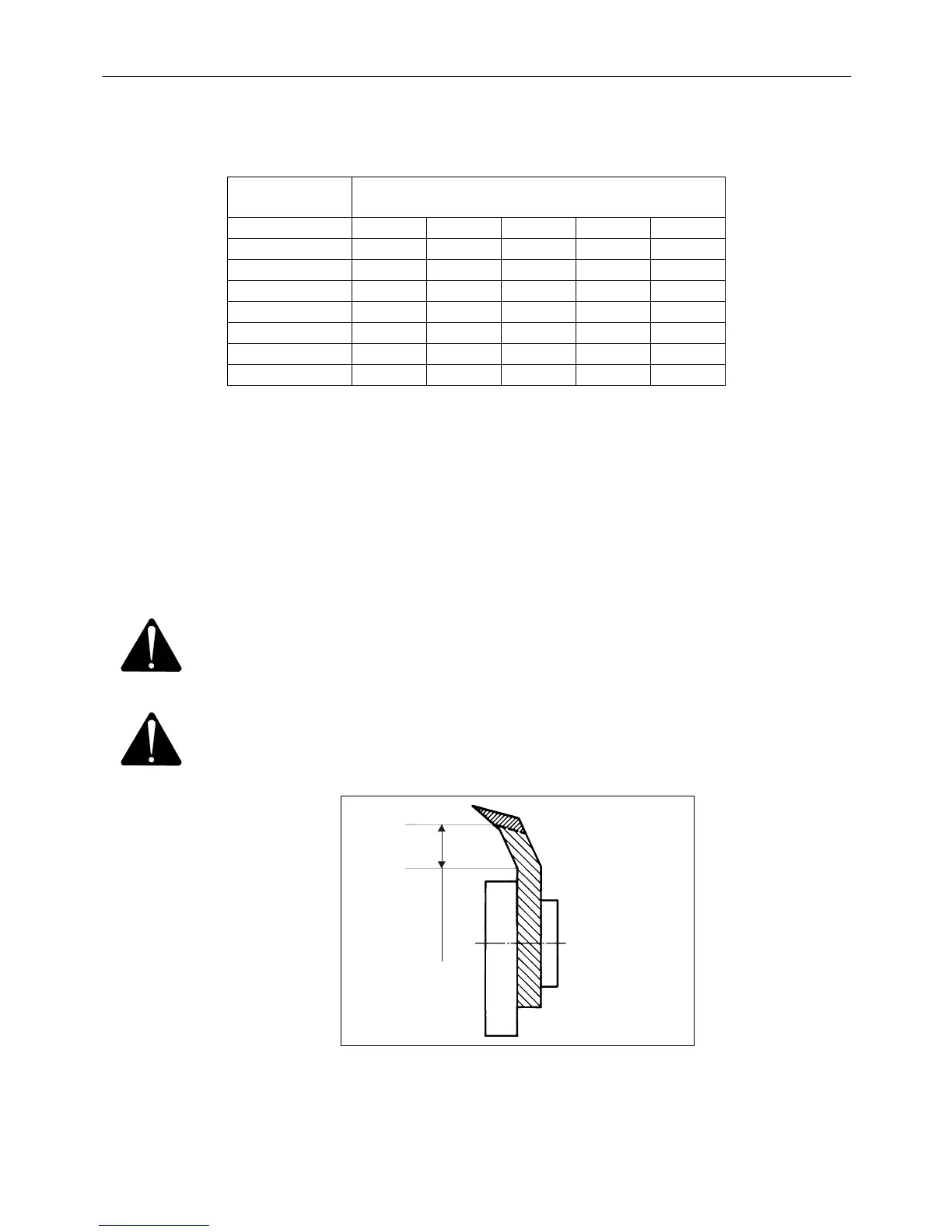
Min. 12 mm
Fig. 4-10
Fig. 4-10 When the blades have been worn max. 8 mm or to the first bend, i.e. approx. 12 mm
above the straight piece they must be replaced.
PIGB-138X-02 FC 855 0410
- 38 -