4. ADJUSTMENTS
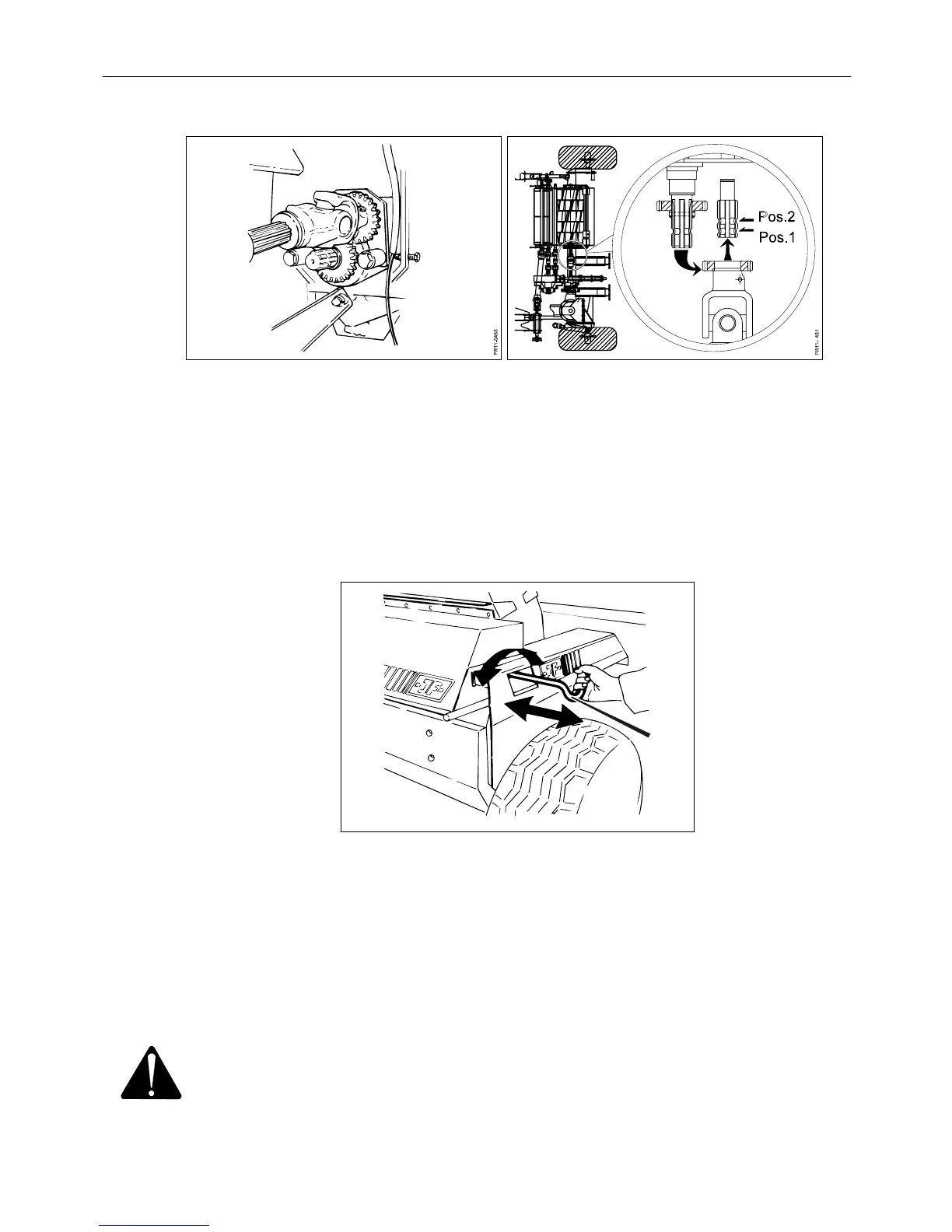
Fig. 4-15
Fig. 4-16
Fig. 4-15 4. Mount the PTO drive shaft for the rotor on the free pin on the rotor housing. The
Fig. 4-16 PTO drive shaft must be fixed at position 2 whereby the rotor will rotate in the
opposite direction.
5. Close all guards.
6. Start the tractor and keep the rpm at a little above idle speed.
PR12-0220
Fig. 4-17
Fig. 4-17 7. Feed carefully by turning the handle A until the stone touches the blade. Move
the stone in a sliding movement across the whole rotor and back again. Feed
some more and repeat the movement across the whole width of the rotor.
8. Push the handle in after grinding. Stop the tractor and when the rotor has come
to a complete stop, the guard between the device and the rotor must be lifted
back into its right position. The PTO drive shaft for the rotor must be moved
back to the pin for normal direction of rotation of the rotor.
WARNING: REMEMBER, only grind with CLOSED guards.
PIGB-138X-02 FC 855 0410
- 41 -