5. DRIVING IN THE FIELD
DANGER: Do not approach the machine until the rotating parts have come
to a complete stop.
PR12-0460
A
B
Fig. 5-5
Fig. 5-4
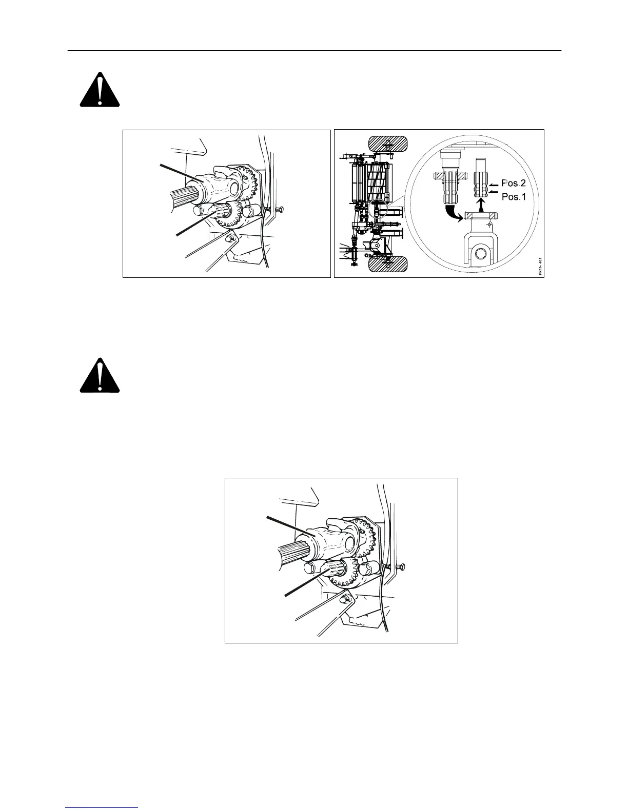
Fig. 5-4 2) Move the PTO shaft A for the rotor to the alternative pin in pos. 1 where the
Fig. 5-5 gear wheels are not in mesh. Thereby the rotor is not driven.
WARNING: It is important that the PTO shaft is NOT moved to pos. 2, where
the rotor rotates in the opposite direction. This position is used
for grinding, or for reverse in case of blockage in the auger or
the feed intake section.
3) Connect the power take-off again at low number of rpm and move the reverse
function to reverse position with the toggle switch on the control panel and
reverse the material out of the machine.
PR12-0460
A
B
Fig. 5-6
Fig. 5-6 4) After reversing disconnect the tractor’s power take-off again, stop the tractor,
and move the PTO shaft A for the rotor back to the pin B for drive of the rotor.
5) The reverse function is brought back to normal feed intake.
6) When the machine runs, increase to correct number of rpm and the work can be
continued.
PIGB-138X-02 FC 855 0410
- 47 -