SECTION 2 - PROCEDURES
2-12 3121801
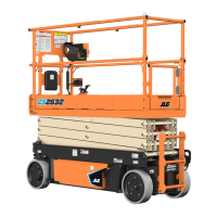
7. If applicable, correctly place new seals and guide lock
rings in the outer piston diameter groove. (A tube, with
I.D. slightly larger than the O.D. of the piston is recom-
mended to install the solid seal.)
NOTE: The backup rings for the solid seal have a radius on one
side. This side faces the solid seal.(See magnified insert in
Figure 2-11.) The split of seals and backup rings are to be
positioned so as not to be in alignment with each other.
8. Using suitable protection, clamp the cylinder rod in a
vise or similar holding fixture as close to piston as possi-
ble.
9. Carefully thread the piston on the cylinder rod hand
tight, ensuring that the o-ring and back-up rings are not
damaged or dislodged.
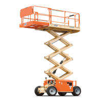
10. Thread piston onto rod until it abuts the spacer end and
install the tapered bushing.
NOTE: When installing the tapered bushing, piston and mating
end of rod must be free of oil.
11. Assemble the tapered bushing loosely into the piston
and insert JLG capscrews (not vendor capscrews)
through the drilled holes in the bushing and into the
tapped holes in the piston.
12. Tighten the capscrews evenly and progressively in rota-
tion to the specified torque value. (See Table 2-1, Cylin-
der Component Torque Specifications.)
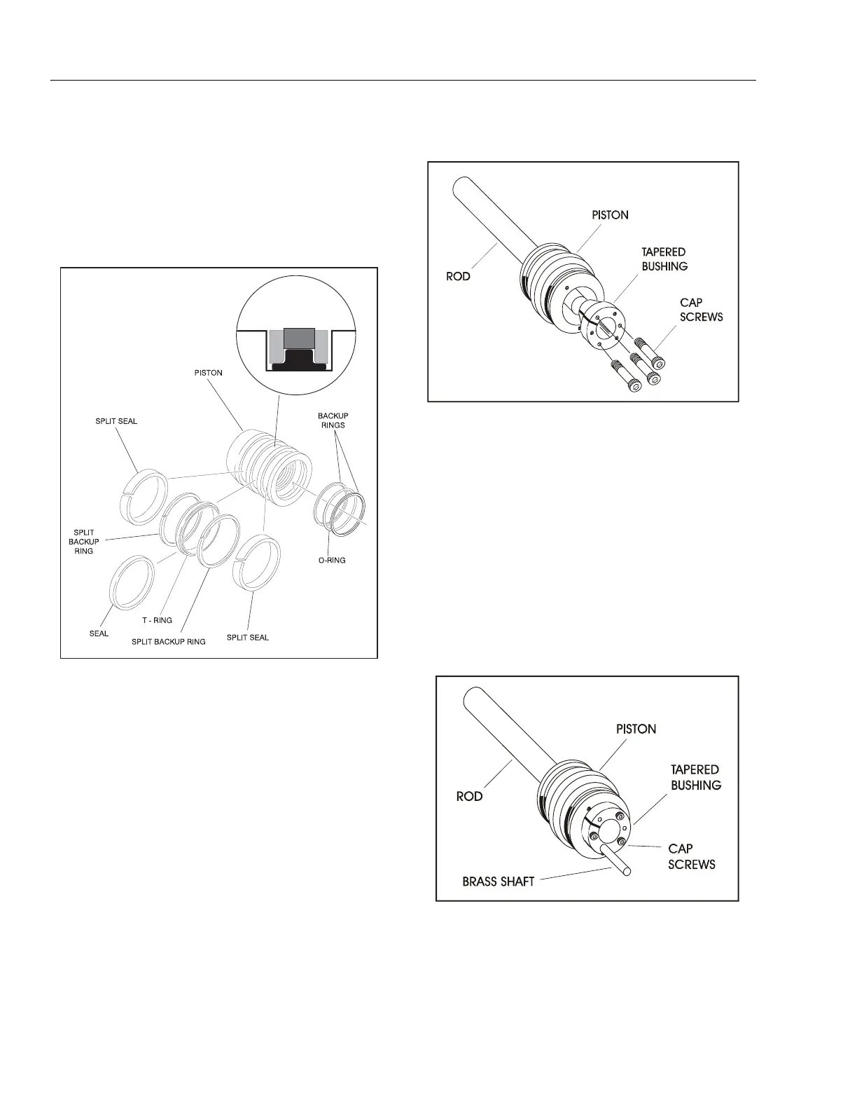
13. After the screws have been torqued, tap the tapered
bushing with a hammer (16 to 24 oz.) and brass shaft
(approximately 3/4" in diameter) as follows;
a. Place the shaft against the cylinder rod and in con-
tact with the bushing in the spaces between the
capscrews.
b. Tap each space once; this means the tapered bush-
ing is tapped 3 times as there are 3 spaces between
the capscrews.
14. Retorque the capscrews evenly and progressively in
rotation to the specified torque value. (SeeTable 2-1, Cyl-
inder Component Torque Specifications.)
15. Remove the cylinder rod from the holding fixture.
Figure 2-11. Piston Seal Kit Installation
Figure 2-12. Tapered Bushing Installation
Figure 2-13. Seating the Tapered Bearing
 Loading...