SECTION 2 - PROCEDURES
3121801 2-13
16. Place new guide locks and seals in the applicable out-
side diameter grooves of the cylinder piston. (See Figure
2-11., Piston Seal Kit Installation )
17. Position the cylinder barrel in a suitable holding fixture.
EXTREME CARE SHOULD BE TAKEN WHEN INSTALLING THE CYLINDER ROD,
HEAD, AND PISTON. AVOID PULLING THE ROD OFF-CENTER, WHICH COULD
CAUSE DAMAGE TO THE PISTON AND CYLINDER BARREL SURFACES.
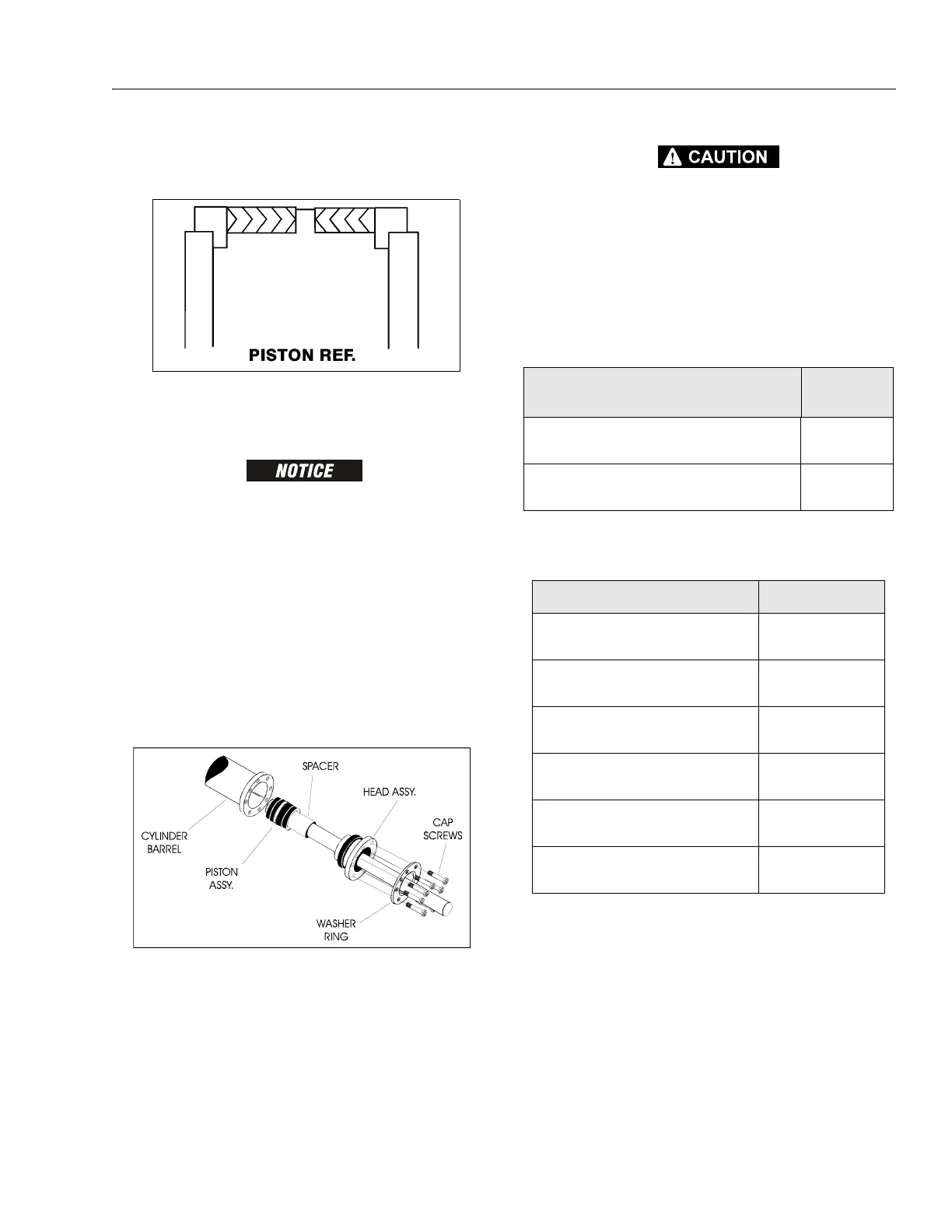
18. With barrel clamped securely, and while adequately sup-
porting the rod, insert the piston end into the barrel cyl-
inder. Ensure that the piston loading o-ring and seal ring
are not damaged or dislodged.
19. Continue pushing the rod into the barrel until the cylin-
der head gland can be inserted into the barrel cylinder.
20. Secure the cylinder head gland using the washer ring
and socket head bolts.
21. After the cylinder has been reassembled, the rod should
be pushed all the way in (fully retracted) prior to the
reinstallation of any holding valve or valves.
22. If applicable, install the cartridge-type holding valve and
fittings in the rod port block, using new o-rings as appli-
cable. (See Table 2-1, Cylinder Component Torque Speci-
fications).
IF THE CYLINDER IS TO BE TESTED PRIOR TO INSTALLATION ON THE MACHINE,
EXTREME CARE SHOULD BE USED TO INSURE THAT THE OUTER END OF THE
ROD IS SUPPORTED. USE EITHER A TRAVELING OVERHEAD HOIST, FORK-LIFT,
OR OTHER MEANS TO SUPPORT THE OVERHANGING WEIGHT OF THE EXTEND-
ING ROD.
23. If applicable, install the cartridge-type holding valve and
fittings in the port block using new o-rings as applica-
ble. (SeeTable 2-2, Holding Valve Torque Specifications).
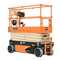
Figure 2-14. Poly-Pak Piston Seal Installation
Figure 2-15. Rod Assembly Installation
Table 2-1. Cylinder Component Torque Specifications
Component
Torque Value
(w/Loctite)
Tapered Bushing Retaining Screws - Lift Cylinder
80 ft lbs
(108 Nm)
Head Retaining Screws - Lift Cylinder
9 ft lbs
(12 Nm)
Table 2-2. Holding Valve Torque Specifications
Description Torque Value
Sun - 7/8 hex M20 x 1.5 thds 30 - 35 ft lbs
(41 - 48 Nm)
Sun - 1-1/8 hex 1 - 14 UNS thds 45 - 50 ft lbs
(61 - 68 Nm)
Sun - 1-1/4 hex M36 x 2 thds 150 - 153 ft lbs
(204 - 207 Nm)
Racine - 1-1/8 hex 1-1/16 - 12 thds 50 - 55 ft lbs
(68 - 75 Nm)
Racine - 1-3/8 hex 1-3/16 - 12 thds 75 - 80 ft lbs
(102 - 109 Nm)
Racine - 1-7/8 hex 1-5/8 - 12 thds 100 - 110 ft lbs
(136 - 149 Nm)
 Loading...