31
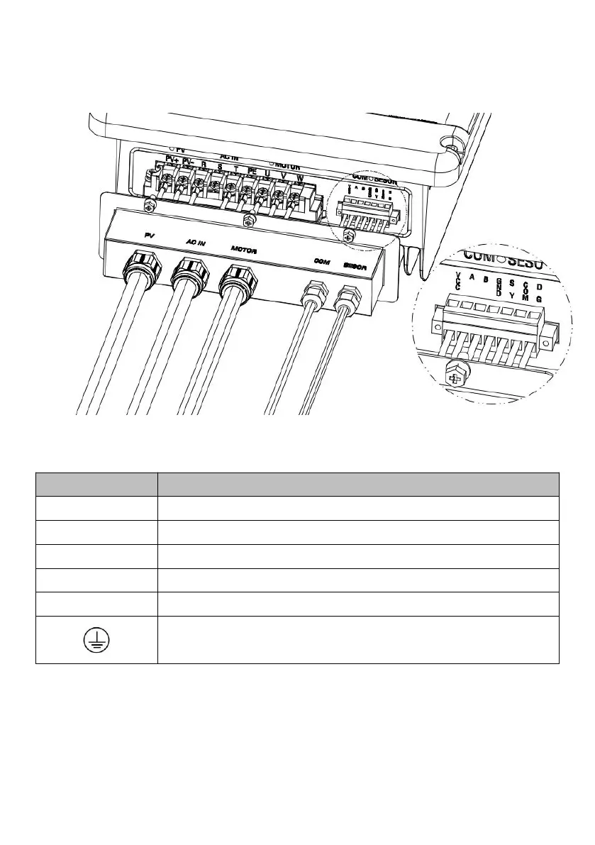
Figure6-1 External connection terminals of inverter
Table6-1 Description
AC input terminals , including R,S,T,PE.
PV array DC input terminals, including PV+,PV-.
Output terminal, connect with AC pump, including U,V,W.
Water level sensor signal input terminal (optional)
RS485 or GPRS communication interface (optional)
Grounding terminal(Grounding screw on the right side of inverter case)
6.2 Schematic Diagram of Electrical Connection
Figure 6-2 is the schematic diagram of electrical connection among PV arrays,