34
Layout
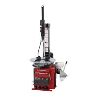
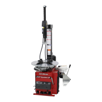
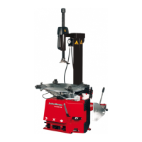
Operator’s Manual QUADRIGA 1000/BB
4.1-2
4.1-4
1
2
4
3
5
6
7
8
9
10
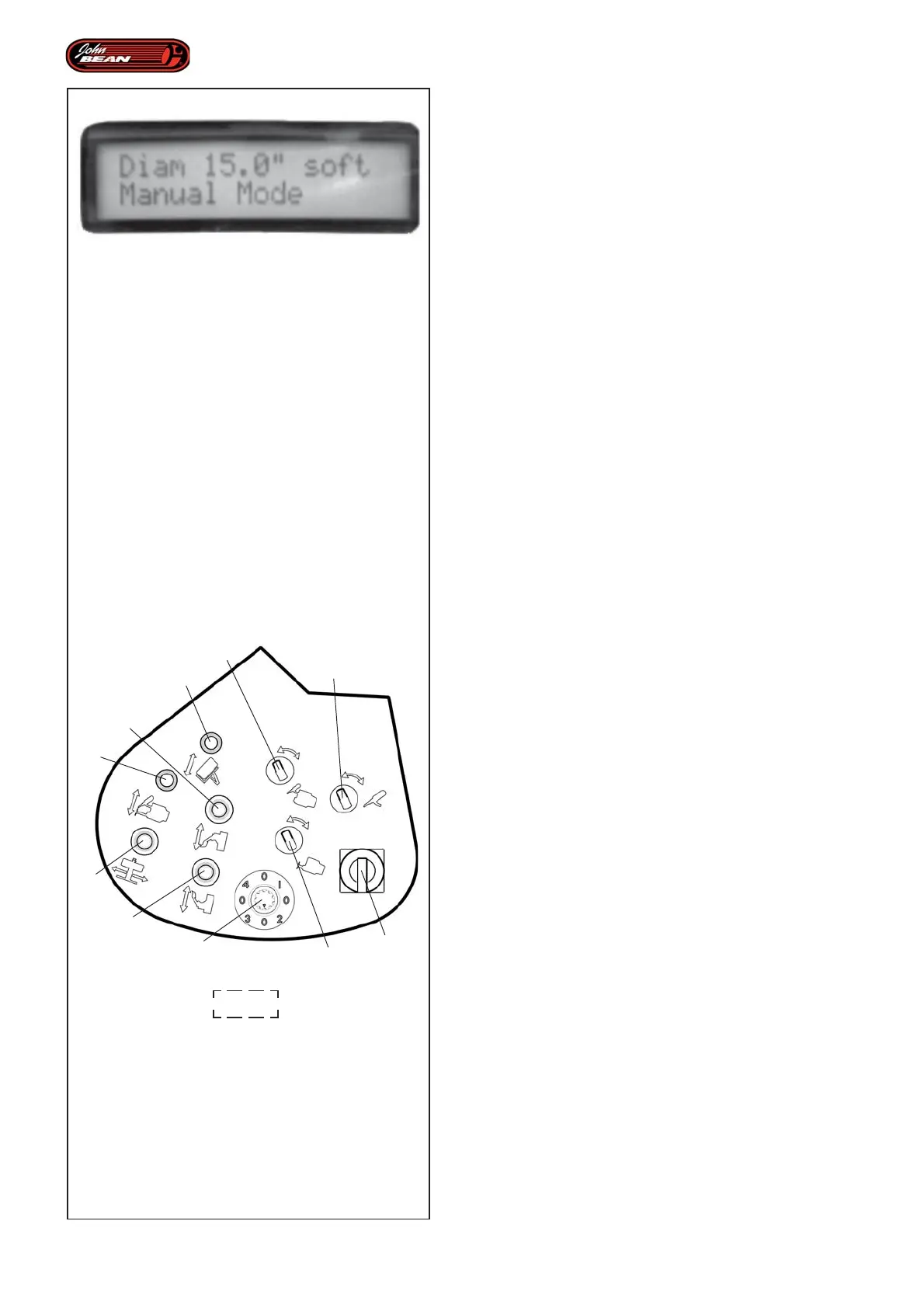
DISPLAY Fig. 4.1-4
The Display shows the rim diameter set, the type of
tire and the current operating mode: MANUAL mode,
AUTOMATIC MOUNTING mode, AUTOMATIC
DEMOUNTING mode, "EXPERT CHOICE" mode.
Figure 4.1-4 shows the Display in operation.
4.1.2 Control Panel
The Control Panel features a series of selectors and
levers that can be used in MANUAL mode to activate
most of the machine components.
When in any AUTOMATIC mode, only this lever (2, Fig.
4.1-2) is enabled to activate the automatic procedure
for moving the tool carriage vertically. For details of how
to use this, see the Individual Automated Parts chapter.
Control Descriptions Figura 4.1-2
Lever 1
This activates the automatic wheel loading and
unloading procedure from the ground to the work
position and viceversa.
Lever 2
This moves the Tool Holder Unit vertically. It also enables
the activation of the automatic procedures.
Lever 3
This moves the Wheel Support (Center Post)
horizontally.
Lever 4
This activates the upper bead breaker disk.
Lever 5
This activates the lower bead breaker disk
Selector 6
This moves tool arm “1”.
Selector 7
This turns tool “1”.
Selector 8
This moves tool arm “2”.
Selector 9 (knob)
This is used to select the “EXPERT CHOICE” mode
automatic subprograms.
10 Main switch
Main on/off switch.