70
Operator’s Manual
Operations
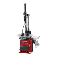
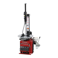
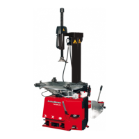
QUADRIGA 1000/BB
5.1-1
5.1-2
4.1-3
2
1
OK
5.1 Wheel Lifter
WARNING: IF THE WHEELS ARE HEAVY USE THE
LIFT DEVICE
5.1.1 Using the Wheel Lifter
Should the user require it, the machine is provided with
a lift device that will raise the wheel or just the rim from
the ground to a suitable working height.
This will prevent any excessive effort or potentially
harmful movements on the part of the operator.
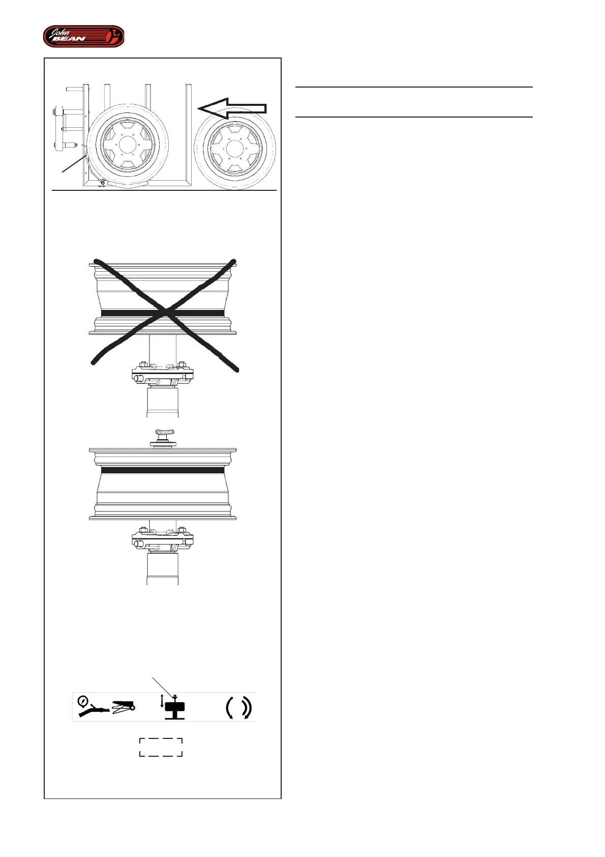
Figure 5.1.1-2
WARNING:
ONCE THE WHEEL HAS BEEN MOUNTED ON THE
FLANGE, THE RIM DROP CENTER MUST ALWAYS
BE POSITIONED HIGH, NEXT TO THE MOUNT/
DEMOUNT TOOL.
5.1.1.1 Loading the wheel
To position the wheel on the front lifter, proceed as
follows:
• Check that the wheel holder flange is free.
• Position the grip pin arm in the closed position
(towards the centre of the flange).
• Check that MANUAL Mode is selected.
• Activate the command (2, Fig. 4.1-3) to move the
rim clamping rod into the right back position.
• Move the wheel up to the front lifter so that the rim
drop center is facing the outside of the machine.
• Load the wheel by rolling it onto the lift device (Fig.
5.1.1-1).
If the wheel positioned on the lift device has an external
diameter that is large enough to activate the Wheel
Sensor Arm (1, Fig. 5.1.1-1), the Load wheel onto Wheel
Holder Flange operation will be enabled and the
movement will be performed automatically by the
machine.
Note: Wheels with small diameters or rims only
have a low weight and as a result of their
size they may not activate the Wheel
Sensor Arm (1, Fig. 5.1.1-1). So these
parts should be located manually on the
tire changer wheel holder flange.