AD-1272 Advanced Thermal Dispersion Probe Airflow Measuring System Technical Bulletin
21
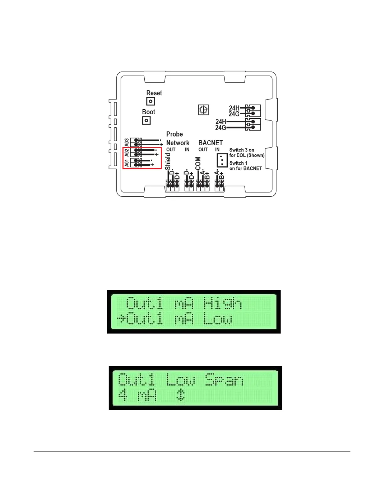
5. Connect a digital multi-meter set to scale Analog Output 1 across terminals plus and minus on the AD-1272
Airflow Measuring System. See Figure 29 for terminal locations.
Note: The output value should be between 1 and 20 mA. To align the load resistance with the digital multi-meter,
connect the actual process load or a resistor of similar value to the actual process load (250 ohm/
minimum). The digital multi-meter should read a minimum value of 4.00 ± 0.01 mA as determined in Output
1 Span.
6. Press UP or DOWN to adjust the output. Once the last digit is entered, the digital multi-meter reflects the
adjusted Output 1 offset value.
7. Press UP or DOWN in the Output Calibration submenu to scroll to the Output 1 mA Low Span submenu
selection.
8. Press ENTER. The display indicates the current Output 1 low span value.
9. Press UP and DOWN to scroll between 1 and 4 mA to set the low span value.
Note: The low span value must be set lower than the high span value.
Figure 29: AD-1272 Airflow Measuring System—Terminals 1 and 2
Figure 30: Output 1 mA Low Selection Screen
Figure 31: Output 1 Low Span Display Screen
 Loading...