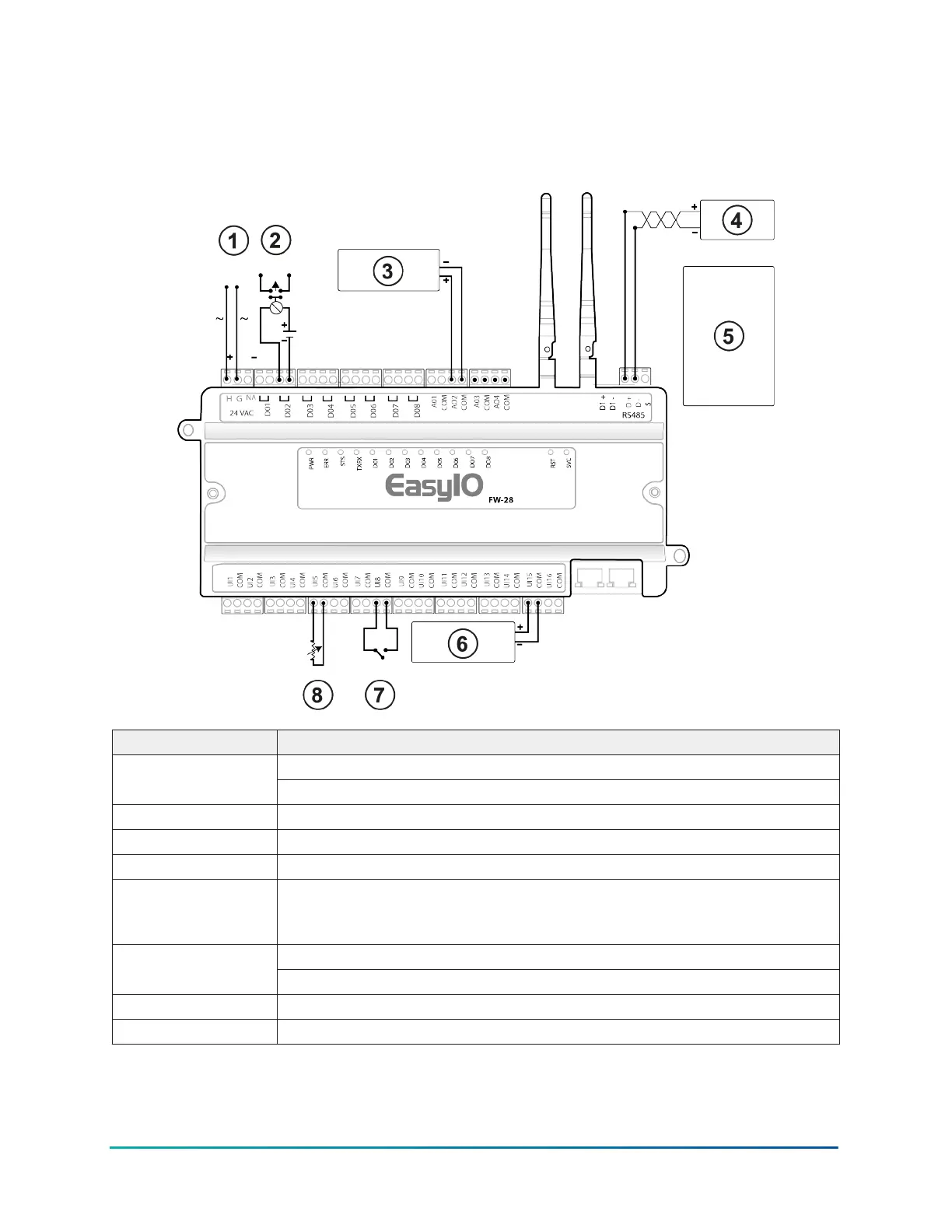
Wiring diagram
Figure 12: FW-28 wiring diagram
The following diagrams shows the controller in a system with a basic setup.
Callout Description
Power input1
24 VAC or 24 VDC
2 External pilot duty relay that the DO activates
3 Voltage-controlled actuator
4 BACnet MS/TP, and Modbus RTU devices
5 120 Ohm resistor. If you configure the controller as a subordinate device
and it is at the end of a daisy chain, install a 120 Ohm resistor in parallel
with the RS-485 terminal.
Voltage transmitter6
0 V to 10 V or 0 V to 5 V
7 Switch
8 Thermistor, RTD, or potentiometer
13EasyIO FW-28 Quick Start Guide